Table of Contents
Advertisement
Advertisement
Table of Contents

Related Manuals for Pepperl+Fuchs PMI360DV-F130-IU-V15


Summary of Contents for Pepperl+Fuchs PMI360DV-F130-IU-V15
- Page 1 PMI360DV-F130-IU-V15 Inductive angle positioning system Manual...
- Page 2 Phone: +49 621 776 - 0 E-mail: info@de.pepperl-fuchs.com North American Headquarters Pepperl+Fuchs Inc. 1600 Enterprise Parkway Twinsburg, Ohio 44087 Phone: +1 330 425-3555 E-mail: sales@us.pepperl-fuchs.com Asia Headquarters Pepperl+Fuchs Pte. Ltd. P+F Building 18 Ayer Rajah Crescent Singapore 139942 Phone: +65 6779-9091 E-mail: sales@sg.pepperl-fuchs.com https://www.pepperl-fuchs.com...
-
Page 3: Table Of Contents
PMI360DV-F130-IU-V15 Contents Introduction........................ 4 Declaration of Conformity..................5 Safety .......................... 6 Symbols Used ....................6 Intended use ....................6 General safety instructions ................6 Product Description ....................7 Use and Applications ..................7 Displays and controls..................8 Delivery package ................... 8 Accessories.................... -
Page 4: Introduction
PMI360DV-F130-IU-V15 Introduction Introduction Congratulations You have chosen a device manufactured by Pepperl+Fuchs. Pepperl+Fuchs develops, pro- duces and distributes electronic sensors and interface modules for the market of automation technology on a worldwide scale. Symbols used The following symbols are used in this manual: Note This symbol draws your attention to important information. -
Page 5: Declaration Of Conformity
This product was developed and manufactured in line with the applicable European standards and directives. Note A declaration of conformity can be requested from the manufacturer. The product manufacturer, Pepperl+Fuchs Group, 68307 Mannheim, Germany, has a certified quality assurance system that conforms to ISO 9001. ISO9001... -
Page 6: Safety
In the event of any serious errors, stop using the device. Secure the device against unintended operation. To have the device repaired, return it to your local Pepperl+Fuchs representative or your sales center. Note Disposal Electronic waste is hazardous. -
Page 7: Product Description
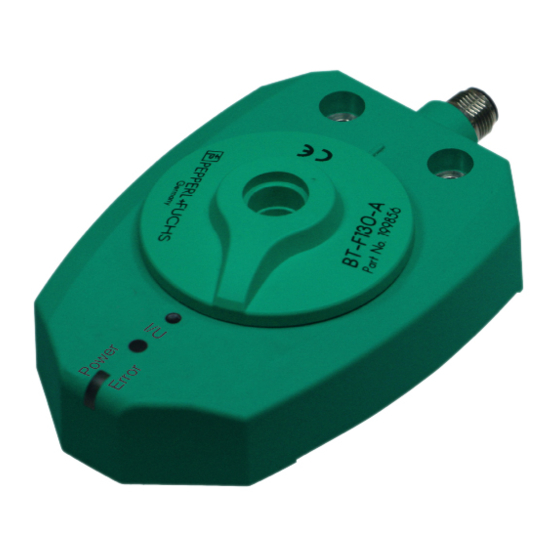
The actuator BT-F130-A (see chapter 4.4) is usually attached to the rotary system component to detect the position. This actuator rotates in the central hole on the PMI360DV-F130-IU-V15, contains a metal insert required for position detection and is adapted perfectly to the mechani- cal requirements of valves or valve actuators. -
Page 8: Displays And Controls
LED indicators Programming button 2 LEDs and 1 programming button are located on top of the PMI360DV-F130-IU-V15. The central, front "Power/Error" LED is a 2-color LED that lights up or flashes green (normal operation) or red (fault) depending on the current operating state of the device. The LED "I/U" is yellow and indicates the status of the device during the programming process and normal oper- ation. -
Page 9: Connection Cables
PMI360DV-F130-IU-V15 Product Description 4.4.1 Connection Cables You can use the following single-ended female cordsets to establish the electrical connection: M12 x 1 single-ended female cordsets, 5-pin Illustration Material Length Model number M12 x 1, straight, 5-pin V15-G-2M-PVC V15-G-5M-PVC 10 m... -
Page 10: Installation
PMI360DV-F130-IU-V15 Installation Installation Note on safety Warning! Risk of short circuit Working on live parts can cause injuries and can compromise the function and the electrical safety of the device. • Before working on the device, always disconnect the supply voltage. - Page 11 PMI360DV-F130-IU-V15 Installation Using a different actuating element The BT-F130-A actuator included can be replaced with a different actuator, provided that the new actuator fits in the sensor opening. When using a different actuator element, the element must fulfill all requirements relating to the material, dimensions and distance to the sensitive surface on the sensor (see table).
-
Page 12: Electrical Connection
Check that the wires are connected correctly before connecting the cordset to the sensor. On Pepperl+Fuchs cordsets, the wire colors are assigned to the connecting pins in the connector according to DIN EN 60947-5-2. Attach the socket on the cordset to the connector on the sensor and tighten the union nut by hand. -
Page 13: Commissioning
PMI360DV-F130-IU-V15 Commissioning Commissioning Programming the analog output The start point of the analog output is preset to the angular position 0° and the end point is pre- set to the angular position 360°in the factory. If the actuator is located in the 0° position, a cur- rent value of 4 mA or a voltage value of 0 V is available at the analog output depending on the connected load. - Page 14 PMI360DV-F130-IU-V15 Commissioning Note Programming an angle segment of exactly 45° If you intend to program an angle segment of exactly 45° for the analog output, you can make use of the restriction that prevents the angle segment from being below 45°...
-
Page 15: Output Function In Normal Operation
PMI360DV-F130-IU-V15 Output function in normal operation Output function in normal operation Example I/U2 I/U1 0° 90° 180° 270° 360° I/U2 I/U1 Figure 7.1 Output function depends on the position of the actuator and the method used to program the output. -
Page 16: Function Of The Analog Output I/U
PMI360DV-F130-IU-V15 Output function in normal operation Function of the Analog Output I/U Function in normal operation The position of the actuator defined by the angular positioning system is based on half of the actuator width (center of the actuator). The start point of the analog output is preset to the angular position 0°... - Page 17 PMI360DV-F130-IU-V15 Output function in normal operation Note Special feature when the system is switched on with a voltage output If a high resistance load is connected to the sensor and the sensor is therefore operating with a voltage output, a special function occurs when the system is switched on in the following...
-
Page 18: Maintenance And Repair
Resetting the output functions to default The resetting process is initiated using the button on the sensor. S0 = 0 ° Default setting PMI360DV-F130-IU-V15 Reset process Press and hold the sensor button. The associated yellow LED starts to flash slowly after 2 seconds. -
Page 19: Troubleshooting
PMI360DV-F130-IU-V15 Troubleshooting Troubleshooting Faults when programming the output If unexpected situations occur when the output of the inductive angular positioning system is programmed, refer to the table below for possible causes and instructions for rectifying the problem. State Possible cause... -
Page 20: Faults During Operation
PMI360DV-F130-IU-V15 Troubleshooting Faults during operation If the inductive angular positioning system does not function correctly, refer to the table below for possible causes and instructions for rectifying the problem. Error Possible cause Action "Power/Error" LED does not The power supply is switched... -
Page 21: Disposal
PMI360DV-F130-IU-V15 Disposal Disposal Electronic waste is hazardous waste. When disposing of the equipment, observe the current statutory requirements in the respective country of use, as well as local regulations. The device does not contain any batteries that require separate disposal. - Page 22 Pepperl+Fuchs Quality Download our latest policy here: www.pepperl-fuchs.com/quality www.pepperl-fuchs.com © Pepperl+Fuchs · Subject to modifications Printed in Germany / DOCT-2048C...
Need help?
Do you have a question about the PMI360DV-F130-IU-V15 and is the answer not in the manual?
Questions and answers