Table of Contents
Advertisement
Quick Links
Advertisement
Table of Contents

Related Manuals for Pepperl+Fuchs PMI360D-F130-IE8-V15


Summary of Contents for Pepperl+Fuchs PMI360D-F130-IE8-V15
- Page 1 PMI360D-F130-IE8-V15 Inductive Position Measuring System Manual...
- Page 2 Phone: +49 621 776 - 0 E-mail: info@de.pepperl-fuchs.com North American Headquarters Pepperl+Fuchs Inc. 1600 Enterprise Parkway Twinsburg, Ohio 44087 Phone: +1 330 425-3555 E-mail: sales@us.pepperl-fuchs.com Asia Headquarters Pepperl+Fuchs Pte. Ltd. P+F Building 18 Ayer Rajah Crescent Singapore 139942 Phone: +65 6779-9091 E-mail: sales@sg.pepperl-fuchs.com https://www.pepperl-fuchs.com...
-
Page 3: Table Of Contents
PMI360D-F130-IE8-V15 Contents Introduction........................ 4 Declaration of Conformity..................5 Safety .......................... 6 Symbols Used ....................6 Intended use ....................6 General safety instructions ................6 Product Description ....................7 Use and application..................7 LED indicators and control buttons............. 8 Scope of supply ..................... 8 Accessories.................... -
Page 4: Introduction
PMI360D-F130-IE8-V15 Introduction Introduction Congratulations You have chosen a device manufactured by Pepperl+Fuchs. Pepperl+Fuchs develops, pro- duces and distributes electronic sensors and interface modules for the market of automation technology on a worldwide scale. Symbols used The following symbols are used in this manual: Note This symbol draws your attention to important information. -
Page 5: Declaration Of Conformity
This product was developed and manufactured in line with the applicable European standards and directives. Note A declaration of conformity can be requested from the manufacturer. The product manufacturer, Pepperl+Fuchs Group, 68307 Mannheim, Germany, has a certified quality assurance system that conforms to ISO 9001. ISO9001... -
Page 6: Safety
In the event of any serious errors, stop using the device. Secure the device against unintended operation. To have the device repaired, return it to your local Pepperl+Fuchs representative or your sales center. Note Disposal Electronic waste is hazardous. -
Page 7: Product Description
PMI360D-F130-IE8-V15 Product Description Product Description Use and application The PMI360D-F130... inductive position measuring system is a high-precision measuring sys- tem for non-contact recording of the position of rotary actuators and valves. But, thanks to the option of user-friendly and flexible configuration, it is also suitable for universal sensing of rotary motions around a fixed center of rotation in all fields of mechanical, system and appara- tus engineering. -
Page 8: Led Indicators And Control Buttons
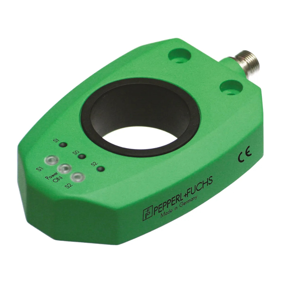
PMI360D-F130-IE8-V15 Product Description LED indicators and control buttons Display LEDs Programming teach-in buttons There are 3 LEDs and 3 programming buttons on the top of the PMI360D-F130..The middle "Power ON" LED is green and lights up when the position measuring system is con- nected to the supply voltage. -
Page 9: Accessories
PMI360D-F130-IE8-V15 Product Description Accessories Various accessories are available. 4.4.1 Connection Cables You can use the following single-ended female cordsets to establish the electrical connection: M12 x 1 single-ended female cordsets, 5-pin Illustration Material Length Model number M12 x 1, straight, 5-pin... -
Page 10: Installation
PMI360D-F130-IE8-V15 Installation Installation Note on safety Warning! Risk of short circuit Working on live parts can cause injuries and can compromise the function and the electrical safety of the device. • Before working on the device, always disconnect the supply voltage. - Page 11 PMI360D-F130-IE8-V15 Installation Dimensions and distances Ø10 Ø5.2 10.3 ± 0.3 41.5 2 mounting holes, length 17 mm M12 x 1 connector, 5-pin Dimension [mm] 23 1 ... 2 2...
-
Page 12: Electrical Connection
Before connecting the cable to the sensor, make sure that you have aligned the cores. On Pepperl+Fuchs connectors, the core colors are assigned to the connection pins in accordance with DIN EN 60947-5-2. Connect the cable to the sensor-side connector and tighten the union nut by hand. -
Page 13: Commissioning
PMI360D-F130-IE8-V15 Commissioning Commissioning Configuration of switching outputs The switching points are set at the factory to the angular positions 30° (S1) and 220° (S2). Con- figuration can be used to locate these switching points at each desired position. To configure... -
Page 14: Configuration Of Analog Output
PMI360D-F130-IE8-V15 Commissioning Configuration of analog output The start point of the analog output is set at the factory to the position angle 0°. When the target is put in this position, a current value of 4 mA is the analog output. You can configure the start point of the analog output at any desired position. -
Page 15: Output Performance In Normal Operation
PMI360D-F130-IE8-V15 Output performance in normal operation Output performance in normal operation Example 0° 90° 180° 270° 360° 6° 6° Figure 7.1 Output performance dependent on the position of the target 1. Marking, angular position 0° (factory setting) 2. Position for programming S1 (example) 3. -
Page 16: Performance Of S0 Analog Output
PMI360D-F130-IE8-V15 Output performance in normal operation Performance of S0 analog output The position of the target is determined by the position measuring system. It is half the target width (middle of target). The start point of the analog output is set at the factory to the position angle 0°. -
Page 17: Maintenance And Repair
PMI360D-F130-IE8-V15 Maintenance and Repair Maintenance and Repair Maintenance The sensor's transmission properties are stable over long periods. For this reason, regular adjustments to, and maintenance on the sensor itself, are not necessary. Nevertheless check in the course of normal maintenance intervals that the sensor, the actuator and the connector are... -
Page 18: Troubleshooting
PMI360D-F130-IE8-V15 Troubleshooting Troubleshooting Errors when programming outputs If you experience difficulties when programming the outputs of the inductive position measuring system, you will find below a list of the possible causes and information on troubleshooting. Fault Cause Rectification Sensor cannot be placed in... -
Page 19: Errors In Normal Operation
PMI360D-F130-IE8-V15 Troubleshooting Errors in normal operation In the event that the inductive position measuring system does not function correctly, you will find below a list of the possible causes and information on troubleshooting. Error Cause Solution "Power ON" LED does not... - Page 20 Pepperl+Fuchs Quality Download our latest policy here: www.pepperl-fuchs.com/quality www.pepperl-fuchs.com © Pepperl+Fuchs · Subject to modifications Printed in Germany 202757 / DOCT-1315A...
Need help?
Do you have a question about the PMI360D-F130-IE8-V15 and is the answer not in the manual?
Questions and answers