
Subscribe to Our Youtube Channel
Related Manuals for Pepperl+Fuchs PMI15V-F166 IO Series


Summary of Contents for Pepperl+Fuchs PMI15V-F166 IO Series
- Page 1 PMI15V-F166-...-IO-... Series Parameterizing Inductive Position Measurement Systems with IO-Link Interface Manual...
- Page 2 Phone: +49 621 776 - 0 E-mail: info@de.pepperl-fuchs.com North American Headquarters Pepperl+Fuchs Inc. 1600 Enterprise Parkway Twinsburg, Ohio 44087 Phone: +1 330 425-3555 E-mail: sales@us.pepperl-fuchs.com Asia Headquarters Pepperl+Fuchs Pte. Ltd. P+F Building 18 Ayer Rajah Crescent Singapore 139942 Phone: +65 6779-9091 E-mail: sales@sg.pepperl-fuchs.com https://www.pepperl-fuchs.com...
-
Page 3: Table Of Contents
PMI15V-F166-...-IO-... Series Contents Introduction........................ 5 Content of this Document ................5 Target Group, Personnel ................5 Symbols Used ....................5 Intended Use ....................6 General Safety Instructions ................6 Product Description ....................8 Use and Application ..................8 Accessories....................9 2.2.1 Damping Element ....................... - Page 4 PMI15V-F166-...-IO-... Series Contents IO-Link Parameterization..................20 SSC.1 Param: SP1 ..................20 SSC.1 Param: SP2 ..................20 SSC.1 Config: Logic ..................20 SSC.1 Config: Mode ..................21 SSC.1 Config: Hyst..................22 SSC.1 Config Ext: SP Offset ................23 SSC.1 Config Ext: Substitute Behavior ............23 SSC.1 Config Ext: Pulse Extension ............24 Switching Signal Characteristics ................25 Window Mode with SP1 and SP2..............25 Centered Window Mode with SP1 and Offset ...........26...
-
Page 5: Introduction
PMI15V-F166-...-IO-... Series Introduction Introduction Content of this Document This document contains information required to use the product in the relevant phases of the product life cycle. This may include information on the following: • Product identification • Delivery, transport, and storage •... -
Page 6: Symbols Used
PMI15V-F166-...-IO-... Series Introduction Symbols Used This document contains symbols for the identification of warning messages and of informative messages. Warning Messages You will find warning messages, whenever dangers may arise from your actions. It is mandatory that you observe these warning messages for your personal safety and in order to avoid prop- erty damage. -
Page 7: General Safety Instructions
In the event of any serious errors, stop using the device. Secure the device against unintended operation. To have the device repaired, return it to your local Pepperl+Fuchs representative or your sales center. Note Disposal Electronic waste is dangerous. -
Page 8: Product Description
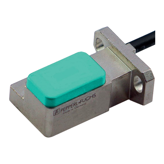
PMI15V-F166-...-IO-... Series Product Description Product Description Use and Application The PMI15V-F166-...-IO-... inductive position measurement system with IO-Link is optimized for highly accurate, continuous position detection. Based on the precise evaluation of several coil systems, the device combines proven inductive sensor technology with innovative micro- controller technology. - Page 9 If you use the "IO-Link Offline Parameterization Tool" software package, have active internet access, and have connected your device via the Pepperl+Fuchs IO-Link USB master, you can integrate the IODD directly into the IO-Link Offline Parameterization Tool via the "IODD DTM Configurator."...
-
Page 10: Accessories
PMI15V-F166-...-IO-... Series Product Description Accessories Various accessories are available. 2.2.1 Damping Element We recommend using the BT-F90-W or BT-F90-G as the damping element. BT-F90-W Material: steel S235 (St37) ø 4,2 BT-F90-G Material: steel S235 (St37) 8 ± 0.1 22 ± 0.2 ø... -
Page 11: Parameterization Aids
PMI15V-F166-...-IO-... Series Product Description Note The exact width of the damping element of 8 mm ± 0.1 mm must be observed. The edges should be broken with a maximum chamfer of 0.1 mm. If the width of the damping element deviates from this value, the position values will differ. -
Page 12: Installation
PMI15V-F166-...-IO-... Series Installation Installation Safety Information Caution! Risk of short circuit Carrying out work while the system is energized may result in damage to the device. • Always disconnect the supply voltage before carrying out work on the device. • Only connect the device to the supply voltage once all work has been completed. -
Page 13: Preparation
Check the package contents against your order and the shipping documents to ensure that all items are present and correct. Should you have any questions, direct them to Pepperl+Fuchs. Retain the original packaging in case the device is to be stored or shipped again at a later date. -
Page 14: Mounting
PMI15V-F166-...-IO-... Series Installation Mounting • A flush mount is possible in metallic and nonmetallic environments. • The distance between the plastic cap on the sensor (measuring range) and the mounting base or fastening screws on the damping element must be at least 3 mm. Watch out for any protruding metal parts such as screw heads when mounting the device. -
Page 15: Connection
The list of electrical connections above represents just some of the products in our range of position measurement systems equipped with IO-Link. The list is not exhaustive. Please refer to the datasheet for the connection diagram for your sensor. This datasheet is available to download from the Pepperl+Fuchs website at www.pepperl-fuchs.com. -
Page 16: Cybersecurity And Decommissioning Information
Ensure that the IO-Link device communicates with the remote station via a point-to-point connection. The product features a proprietary Pepperl+Fuchs service interface for production purposes that uses the existing connection lines. Once switched on, the interface is deactivated after <... -
Page 17: Commissioning
PMI15V-F166-...-IO-... Series Commissioning Commissioning Commissioning with IO-Link on a Control Panel (Online Parameterization) Note The device description file (IODD) required for integration in an IO-Link system and for the parameterization and diagnosis is available online. Visit www.pepperl-fuchs.com and navigate to the relevant product page for the PMI15V-F166-...-IO-..To activate the position measurement system via IO-Link using a control panel, proceed as fol- lows: Check the connection between the position measurement system and the IO-Link master. -
Page 18: Commissioning With Io-Link Via Fdt Framework Program (Offline Parameterization)
If the "IO-Link Offline Parameterization Tool" software package is used, there is active internet access, and the device is connected via the Pepperl+Fuchs IO-Link USB master, the IODD can be directly integrated into the IO-Link Offline Parameterization Tool via the "IODD DTM Config- urator."... -
Page 19: Process Data Structure
PMI15V-F166-...-IO-... Series Process Data Structure Process Data Structure The process data of the position measurement system consists of 32 bits (4 bytes). The follow- ing table provides an overview of the order and structure of the process data. Name Data Type Length Bit Offset Value... -
Page 20: Ssc.2-Switching Signal
PMI15V-F166-...-IO-... Series Process Data Structure SSC.1—Switching Signal Switching Signal Channel 1—Switching Signal The "SSC.1—Switching Signal" process data content refers to a signal bit used to detect a position that is critical for the application. It is part of the cyclic signal transmission. Depending on the status of the position measurement system or the state of the application, the signal bit can have the value "0"... -
Page 21: Io-Link Parameterization
PMI15V-F166-...-IO-... Series IO-Link Parameterization IO-Link Parameterization Only the parameters of the PMI15V-F166-...-IO-... product group that require explanation are listed below. Note A comprehensive overview of all parameters for the respective position measurement system can be found online at www.pepperl-fuchs.com. Navigate to the relevant product page for the PMI15V-F166-...-IO-... -
Page 22: Ssc.1 Config: Logic
PMI15V-F166-...-IO-... Series IO-Link Parameterization SSC.1 Config: Logic Switching Signal Channel 1 Configuration Logic Index Parameter Access Data Type Length 61 (0x3D) SSC.1 Config: Logic UInteger 8 bits The "SSC.1 Config: Logic" parameter indicates whether the "SSC1" switching signal is trans- mitted as "high active"... - Page 23 PMI15V-F166-...-IO-... Series IO-Link Parameterization Window Mode SP 2 SP 1 active inactive SP.min SP.max Figure 7.3 Two Point Mode SP 2 SP 1 active inactive SP.min SP.max Figure 7.4 Centered Window Mode SP 1 active Offset Offset inactive SP.min SP.max Figure 7.5 Note SP2 has no effect in this mode.
-
Page 24: Ssc.1 Config: Hyst
PMI15V-F166-...-IO-... Series IO-Link Parameterization SSC.1 Config: Hyst Switching Signal Channel 1 Configuration: Hysteresis Index Parameter Access Data Type Length 61 (0x3D) SSC.1 Config: Hyst Integer 16 bits The "SSC.1 Config: Hysteresis" parameter indicates the extent of a desired delayed effect of the SSC1 bit. -
Page 25: Ssc.1 Config Ext: Sp Offset
PMI15V-F166-...-IO-... Series IO-Link Parameterization SSC.1 Config Ext: SP Offset Switching Signal Channel 1 Extended Configuration Setpoint Offset Index Parameter Access Data Type Length 64 (0x40) SSC.1 Config Ext: SP Offset Integer 16 bits The "SSC.1 Config Ext: SP Offset" parameter is used to set the window width in Centered Win- dow mode. -
Page 26: Ssc.1 Config Ext: Pulse Extension
PMI15V-F166-...-IO-... Series IO-Link Parameterization SSC.1 Config Ext: Pulse Extension Switching Signal Channel 1 Extended Configuration: Pulse Extension Index Parameter Access Data Type Length 64 (0x40) SSC.1 Config Ext: Pulse Extension rw UInteger 8 bits With the "SSC.1 Config Ext: Pulse Extension" parameter, you can extend active phases (with active high signal) or inactive phases (with active low signal) of the switching signal channel 1 where required. -
Page 27: Switching Signal Characteristics
PMI15V-F166-...-IO-... Series Switching Signal Characteristics Switching Signal Characteristics The following sections use examples to describe the switching signal characteristics of the inductive position measurement system for the "SSC.1—Switching Signal 1" process data. The switching signal characteristics for the "SSC.2—Switching Signal 2" process data work in the same way. -
Page 28: Centered Window Mode With Sp1 And Offset
PMI15V-F166-...-IO-... Series Switching Signal Characteristics The general rule for switch points SP1 and SP2 is: Switch points SP1 and SP2 can be set independently of one another. • SP1 can be greater than SP2 • SP1 can be smaller than SP2 •... -
Page 29: Hysteresis With Sp1 And Sp2
PMI15V-F166-...-IO-... Series Switching Signal Characteristics Hysteresis with SP1 and SP2 You can set a uniform hysteresis area for each of the switch points SP1 (setpoint 1) and SP2 (setpoint 2). Keep in mind that the hysteresis limit for Window mode and Centered Window mode has an outward-facing effect. -
Page 30: Maintenance And Repair
PMI15V-F166-...-IO-... Series Maintenance and Repair Maintenance and Repair Maintenance The sensor's transmission properties are stable over long periods. For this reason, regular adjustments to, and maintenance on the sensor itself, are not necessary. Nevertheless check in the course of normal maintenance intervals that the sensor, the actuator and the connector are securely attached. -
Page 31: Troubleshooting
PMI15V-F166-...-IO-... Series Troubleshooting Troubleshooting 10.1 What to Do in Case of a Fault In case of a fault, use the following checklist to determine whether a fault with the sensor can be remedied. If none of the information provided in the checklist solves the problem, you can contact Pep- perl+Fuchs via your sales office with any queries. - Page 32 Pepperl+Fuchs Quality Download our latest policy here: www.pepperl-fuchs.com/quality www.pepperl-fuchs.com © Pepperl+Fuchs · Subject to modifications / DOCT-7034A...
Need help?
Do you have a question about the PMI15V-F166 IO Series and is the answer not in the manual?
Questions and answers