Table of Contents
Advertisement
Quick Links
75/80 Meter
Full Size
Quarter-Wave
Vertical Antenna
DXE-7580FS-VA-3
US Patent No. 8,130,168
DXE-7580FS-VA -3-INS Revision 1
© DX Engineering 2012
P.O. Box 1491 ∙ Akron, OH 44309-1491 USA
Phone: (800) 777-0703 ∙ Tech Support and International: (330) 572-3200
Fax: (330) 572-3279 ∙ E-mail: DXEngineering@DXEngineering.com
Advertisement
Table of Contents

Related Manuals for DX Engineering DXE-7580FS-VA


Summary of Contents for DX Engineering DXE-7580FS-VA
- Page 1 Quarter-Wave Vertical Antenna DXE-7580FS-VA-3 US Patent No. 8,130,168 DXE-7580FS-VA -3-INS Revision 1 © DX Engineering 2012 P.O. Box 1491 ∙ Akron, OH 44309-1491 USA Phone: (800) 777-0703 ∙ Tech Support and International: (330) 572-3200 Fax: (330) 572-3279 ∙ E-mail: DXEngineering@DXEngineering.com...
-
Page 2: Table Of Contents
Lowering or Raising the Vertical Element Assembly Feedline Connection Optional DXE-VMN-1 Vertical Antenna Matching Network Tuning the Vertical Locking the Pivot Base DXE-7580FS-VA-3 Part Lists Pivot Base Assembly Optional DXE-VRW-1 Manual Winch Assembly Feedpoint Hardware Vertical Elements Assembly Exploded View of Pivot Base Assembly for Reference... -
Page 3: Introduction
Quarter-Wave Vertical Antenna! Now you can have a high-performance vertical antenna specifically for the 75/80 meter bands! The DX Engineering 68 foot vertical antenna supplies the highest possible performance. Achieve the strongest possible presence at your power level and be... -
Page 4: Warning
The optional DXE-VRW-1 Manual Winch for easy one-person raising and lowering of the antenna is available from DX Engineering. You can move the DXE-VRW-1 winch between similar antennas in a multi-antenna installation. This antenna system requires a heavy duty mounting pipe. Recommended installation should provide for a 3"... -
Page 5: Manual Updates And Information
Every effort is made to supply the latest manual revision with each product. Occasionally a manual will be updated between the time your DX Engineering product is shipped and when you receive it. Please check the DX Engineering web site (www.dxengineering.com) for the latest revision manual. -
Page 6: Coaxial Cable To Mounting Pipe
On Line Metal Store: www.onlinemetals.com Speedy Metals: www.speedymetals.com Metals Depot: www.metalsdepot.com Note: DX Engineering does not recommend or endorse any specific vendor. This mounting pipe must be permanently mounted in the ground, preferably in a concrete base 2 feet by 2 feet by 4 feet deep (with gravel below for drainage). -
Page 7: Assembly Notes
Grass will quickly overgrow the radials and it will be virtually impossible to see them. An article describing this process is available on the DX Engineering website in the Tech Info section. Radials can also be buried just under the surface by using a power edger to make a slit in the soil. -
Page 8: Radial Plate To Mounting Pipe
Radial Plate to Mounting Pipe Place the optional DXE-RADP-3 Radial Plate over the 3" OD (maximum) mounting pipe. Attach the Radial Plate to the mounting pipe using one DXE-SSVC-3P stainless steel V-Clamp. Allow approximately one inch clearance between the bottom of the Radial Plate and the ground to allow access to the radial wire mounting hardware (see Figure 1). -
Page 9: Attaching Ground Radial Wires To The Radial Plate
Figure 2. Additional hardware kits are available (DXE-RADP-1HWK) that contain 20 sets of Radial Plate Hardware. There are optional DX Engineering Radial Wire Kits available. DXE-RADW-500K/BD contains a 500 foot spool of 14 gauge copper stranded wire with black PVC insulation, 20 Terminal Lugs and 100 Steel or Biodegradable Lawn Staples. -
Page 10: Overall Pivot And Antenna Base Assembly Reference Drawing
Figure 3 Overall Super Duty+ Pivot Base (US Patent No. 8,130,168) Assembly Reference Drawing - 9 -... -
Page 11: Pivot Base And Lower Antenna Assembly
Pivot Base and Lower Antenna Assembly ® 1. Locate the heavy duty Extren insulated channel. There are 14 holes drilled in the insulated channel. The top of the insulated channel is identified by the two wide spaced holes located very near the top end. 2. - Page 12 4. Locate the stainless steel pivot base locking plate, backing plate, four carriage bolts, four 3/8" flat washers, four 3/8" split lock washers and four 3/8" hex nuts. Assemble the pivot base locking plate to the top of the heavy duty Extren® insulated channel as shown below. Tighten the hardware.
- Page 13 6. Locate two 3” cast saddle blocks, two stainless steel 3”x3/8”x5.25” U-Bolts, four stainless steel 3/8" flat washers, four stainless steel 3/8" split lock washers and four stainless steel 3/8"-16 hex head nuts. (Note: The U-Bolts and their hardware may be packaged separately). Loosely assemble (one or two threads beyond the end of the hex nuts) the two U-Bolts to the stainless steel base side bottom hinge as shown below.
- Page 14 8. Locate two 3” cast saddle blocks, two stainless steel 3”x3/8”x5.25” U-Bolts, four stainless steel 3/8" flat washers, four stainless steel 3/8" split lock washers and four stainless steel 3/8"-16 hex head nuts. (Note: The U-Bolts and their hardware may be packaged separately). Loosely assemble (one or two threads beyond the end of the hex nuts) the two U-Bolts to the Pivot Base Winch Mount as shown below.
- Page 15 10. Move the four U-Bolts out as far as they will go (these were put on loosely in steps 2 and 8). Slide the entire assembly onto your mounting pipe. You want approximately 1 inch clearance from the top of your mounting pipe to the bottom side of the winch mounting plate. Position the base fixture in the position you pre-selected for the pivoting direction.
- Page 16 11. Locate the 4" OD x 72", .120 wall thickness antenna bottom element section. There are 5 holes drilled in this element section. Four drilled holes at the top are used for mating to the next antenna element section. One hole is drilled near the bottom for the feed point connection. Loosen the previously installed U-Bolts (Step 9).
- Page 17 12. Locate the stainless steel Antenna Hook Mounting Plate, two 4” U-Bolt Saddle blocks, two 4” x 3/8” x 5.563” stainless steel U-Bolts, four stainless steel 3/8" flat washers, four stainless steel 3/8" split lock washers and four stainless steel 3/8"-16 hex head nuts. (Note: The U-Bolts and their hardware may be packaged separately).
- Page 18 15. Locate the 1/4"-20 x 1" long stainless steel hex bolt, three 1/4" stainless steel external tooth lock washers, two 1/4" stainless steel flat washers and two stainless steel 1/4"-20 hex nuts. Install the feedpoint hardware at the bottom of the 4" OD bottom element in the pre-drilled hole as shown below.
-
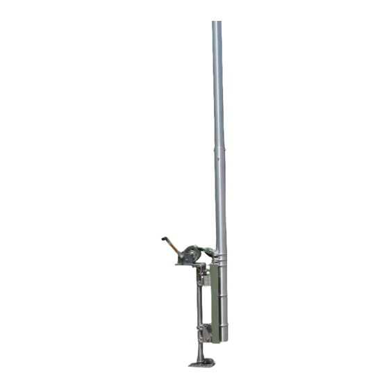
Page 19: Mounting And Using The Optional Dxe-Vrw-1 Manual Winch
Mounting and using the Optional DXE-VRW-1 Manual Winch 1. Follow the instructions included with the optional DXE-VRW-1 - Manual Winch Add-On Kit to prepare the Manual Winch for installation on the antenna base assembly. 2. Included with optional DXE-VRW-1 - Manual Winch Add-On Kit is the stainless steel hardware for mounting the winch on the pivot base assembly. - Page 20 There are three holes with slots in the mounting bracket. The flat washers will fit through the large holes. Once in place, push the winch inward (toward the antenna elements) allowing the three bolts to go into the three slots. Tighten the hardware to hold the winch in place. Connect the Hook from the manual winch strap to the Antenna Hook Mount as shown below.
- Page 21 3. To lower the antenna, ensure the winch hook is in the Antenna Hook Mount. Remove the four bolts and hardware that hold the Pivot Lock Plate to the Pivot Base Winch Mount Plate. You can now use the winch to pivot the antenna downward. Four Bolts to be removed to allow for pivoting 4.
-
Page 22: General Information About Aluminum Tubing
Deburring is a finishing method used in manufacturing. Our aluminum tubing is machine cut on both ends and machine slit on one end. Although DX Engineering manufactured aluminum tubing is deburred, you should further assure that there are no ragged edges or protrusions. -
Page 23: Assembling The Vertical Sections
Assembling the Vertical Sections Note: DXE-P8A -Penetrox A Anti-Oxidant should be used between all antenna element sections. Penetrox is an electrical joint compound to affect a substantial electrical connection between metal parts such as telescoping aluminum tubing or other antenna pieces. - Page 24 - 23 -...
- Page 25 Figure A-1 below is an overall layout of all the vertical elements with hardware shown for reference. The 4" OD element which is already mounted on the base pivot assembly is shown for reference. Figure A-1 - 24 -...
- Page 26 Pivot the antenna base down. This will allow easy assembly of the vertical sections. The further toward the top you go, you will need to have a support under the sections to keep them straight while you do the assembly. Assemble the 3.5"...
- Page 27 The following drilled sections are drilled to match the next size, so make sure you have the correct ends matched up (holes aligned). Assemble the 2.75" OD element to the 3" OD base element using the two stainless steel 1/4-20 x 3- 1/2"...
- Page 28 Using a tape measure and felt tip pen all of the slit tubing elements need to be marked as follows for overlap as shown in Figure A-5. Figure A-5 - 27 -...
- Page 29 Using Figure A-1, place the element clamps over the appropriate tubing. When tightening the element clamps, install them approximately 1/4" to 1/2" below the end of the slit tube with the worm tightening drive as shown in Figure A-6, located between two of the four slits.
-
Page 30: Lowering Or Raising The Vertical Element Assembly
Lowering or Raising the Vertical Element Assembly 1. To lower the antenna, ensure the winch hook is in the Antenna Hook Mount. Remove the four bolts and hardware that hold the Pivot Lock Plate to the Pivot Base Winch Mount Plate. You can now use the winch to pivot the antenna downward. -
Page 31: Feedline Connection
Feedline Connection The easiest way to make a reliable feedline connection using customer supplied coaxial cable is using the optional DXE-RADP-3 Radial Plate with the optional DXE-112-KIT SO-239 Chassis Mount Connector as shown in Figure F-1. Use a customer supplied insulated wire soldered on the center pin of the chassis mounted SO-239 (14 gage insulated wire is adequate) to a ring terminal which is connected to the antenna feedpoint hardware (See page 15). -
Page 32: Tuning The Vertical
The DXE-7580FS-VA-3 should resonate at approximately 3.65 MHz with the recommended ground radial system installed and the vertical dimensions described in this manual. Resonance is adjusted by the length of the vertical element sections. -
Page 33: Locking The Pivot Base
Locking the Pivot Base To help prevent accidental pivoting, ensure the four pivot locking bolts are in place and properly secured. Additionally, you may replace one of the bolts with a padlock to further prevent tampering or accidental pivoting as shown below. Ensure all four Pivot Locking Bolts are in place Padlock used in place of one Pivot Locking Bolt - 32 -... -
Page 34: Dxe-7580Fs-Va-3 Part Lists
DXE-7580-VA-3 Parts List Pivot Base Assembly - US Patent No. 8,130,168 Description 4” Base Side Bottom Hinge 4” Antenna Side Bottom Hinge 4” Bottom Hinge Bushing ® Insulator 10” x 1/2” x 29.625” Heavy Duty Extren Saddle Backing Plate 1.5” x .375” x 8” 4”... -
Page 35: Vertical Elements Assembly
Vertical Elements Assembly Description 4.00” OD x 71.75” long, .25” wall, 5 drilled holes 3.50” OD x 71.75” long, .25” wall, 8 drilled holes 3.00" OD x 72" long, .120” wall, 8 drilled holes 2.75" OD x 48" long, .120 wall, 4 drilled holes 2.75"... -
Page 36: Exploded View Of Pivot Base Assembly For Reference
Exploded View of Pivot Base Assembly for Reference Description 4” Base Side Bottom Hinge 4” Antenna Side Bottom Hinge 4” Bottom Hinge Bushing ® Insulator 10” x 1/2” x Heavy Duty Extren 29.625” Saddle Backing Plate 1.5” x .375” x 8” 4”... -
Page 37: Additional Material Required But Not Supplied
Made from Laser Cut Stainless Steel with 20 Sets of Stainless Steel Radial Attachment Hardware. The DX Engineering Radial Plate is meant for those of you having a vertical antenna and want an easy, neat and effective way to connect those essential radial wires to your antenna system for the highest efficiency and strongest signals. -
Page 38: Optional Accessory Items
Perfect for use with the DX Engineering Radial Plate, (DXE-RADP-3) it ensures the radial ground system, the antenna ground and the feedline shield are common. Don't forget to waterproof coaxial connections. - Page 39 SUM-900031 - Automatic Wire Stripper/Crimper/Cutter, 24-10 Ga. Our DX Engineering wire stripper uses a spring-loaded design to make quick work of wires ranging from 24 to 10 gauge. Just insert the wire, squeeze the handle, and listen for the click. That’s the sound of another perfect wire stripping job performed in about 2 seconds- a fraction of the time it takes your pocket knife to do the same job.
-
Page 40: Technical Support
Warranty All products manufactured by DX Engineering are warranted to be free from defects in material and workmanship for a period of one (1) year from date of shipment. DX Engineering’s sole obligation under these warranties shall be to issue credit, repair or replace any item or part thereof which is proved to be other than as warranted;...
Need help?
Do you have a question about the DXE-7580FS-VA and is the answer not in the manual?
Questions and answers