Table of Contents
Advertisement
Quick Links
Vertical Antenna
for use with
Hi-Z Antennas'
Receive Antenna Systems
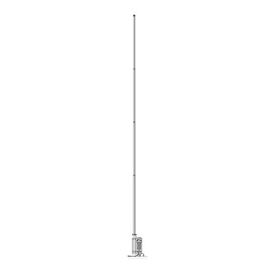
DXE-AL24
DXE-AL24-INS-Revision 2
DXE-AL-24 shown with
Optional Hi-Z amplifier installed
© DX Engineering 2018
1200 Southeast Ave. - Tallmadge, OH 44278 USA
Phone: (800) 777-0703 ∙ Tech Support and International: (330) 572-3200
Fax: (330) 572-3279 ∙ E-mail:
DXEngineering@DXEngineering.com
Advertisement
Table of Contents

Related Manuals for DX Engineering DXE-AL24


Summary of Contents for DX Engineering DXE-AL24
- Page 1 Receive Antenna Systems DXE-AL24 DXE-AL24-INS-Revision 2 DXE-AL-24 shown with Optional Hi-Z amplifier installed © DX Engineering 2018 1200 Southeast Ave. - Tallmadge, OH 44278 USA Phone: (800) 777-0703 ∙ Tech Support and International: (330) 572-3200 Fax: (330) 572-3279 ∙ E-mail: DXEngineering@DXEngineering.com...
-
Page 2: Table Of Contents
Table of Contents Introduction Features Manual Updates Warning Tools Required DXE-AL24 Parts List Additional Material Needed, Not Supplied Suggested Parts Not Included Installation Site Selection Mounting Pipe Assembly Mounting Plate Assembly Assembling the Vertical Sections Element Assembly Mating the Vertical Elements to the Mounting Plate... -
Page 3: Introduction
Every effort is made to supply the latest manual revision with each product. Occasionally a manual will be updated between the time your DX Engineering product is shipped and when you receive it. Please contact DX Engineering (DXEngineering@DXEngineering.com) for the latest revision manual. -
Page 4: Warning
WARNING! INSTALLATION OF ANY ANTENNA NEAR POWER LINES IS DANGEROUS Warning: Do not locate the antenna near overhead power lines or other electric light or power circuits, or where it can come into contact with such circuits. When installing the antenna, take extreme care not to come into contact with such circuits, because they may cause serious injury or death. -
Page 5: Dxe-Al24 Parts List
DXE-AL24 Parts List Description Antenna Mounting Plate, Aluminum 2" V-Saddle Clamp, Stainless Steel with Stainless Steel Hardware 0.75" Saddle Clamp, Cast Aluminum with Stainless Steel Hardware 10-24 x 3/4" Long Hex Head Bolt, Stainless Steel #10 Flat Washer, Stainless Steel... -
Page 6: Installation
Installation Site Selection Select a mounting location clear from power lines, structures and other antennas by a minimum of 24 feet. Consider overhead power lines, utility cables and wires. The vertical should be mounted away from local noise sources or other metallic objects which can re-radiate noise and affect the receive antenna performance. -
Page 7: Assembly
Assembly The DXE-AL24 shipping boxes contain the vertical tubing element sections, mounting plate, two DXE-SSVC-2P 2" V-Bolt assemblies, two cast aluminum saddle clamps, three stainless steel element clamps, two custom wire assemblies with ring terminals, one stainless steel element clamp with welded stud, one solid fiberglass mating rod, a black vinyl cap and stainless steel hardware. - Page 8 Locate the Aluminum Mounting Plate and the two 3/4” U-Bolt Cast Aluminum Saddle Clamps with stainless steel mounting hardware. Loosely assemble the two Cast Aluminum Saddle Clamps to the mounting plate as shown in Figure 2. Figure 2 - Aluminum Saddle Clamps Install the solid Fiberglass Rod through the two aluminum Saddle Clamps as shown in Figure 3.
- Page 9 Locate the two DXE-SSVC-2P Stainless Steel V-Clamps and stainless steel mounting hardware. Loosely install the two V-Clamps on the back side of the mounting plate as shown in Figure 4. Figure 4 - V-Saddle Clamp Installation To mount the optional Hi-Z Plus-6 High Impedance Amplifier to the mounting plate, the four screws that hold the lid on the case need to be removed and replaced with longer screws that go through the Mounting Plate and secure the amplifier.
- Page 10 Turn the case over and place the optional Hi-Z Plus-6 High Impedance Amplifier on the mounting plate as shown in Figure 6. Note the position of the two threaded studs and the label on the optional Hi-Z Plus-6 High Impedance Amplifier when properly placed on the Mounting Plate. While holding the optional Hi-Z Plus-6 High Impedance Amplifier case and lid firmly in place, install the four new metric screws (Stainless Steel Machine Screw, Metric M4 x 40 mm, Phillips Pan Head ) through the Mounting Plate into the Hi-Z Plus-6 High Impedance Amplifier.
-
Page 11: Assembling The Vertical Sections
Deburring is a finishing method used in manufacturing. Our aluminum tubing is machine cut on both ends and machine slit on one end. Although DX Engineering manufactured aluminum tubing is deburred, you should further assure that there are no ragged edges or protrusions. -
Page 12: Element Assembly
Clean the inside of the aluminum tubing to clear out any dirt or foreign material that would cause the aluminum tubing sections to bind during assembly. Do not use any type of oil or general lubricant between the aluminum tubing sections. Oils or general lubricants can cause poor electrical connections for radio frequencies. - Page 13 Locate the three Stainless Steel Element Clamps. Stainless Steel Element Clamp Quantity 0.875” (7/8”) - Element Clamp, 5/16 Drive Nut 0.75” (3/4”) - Element Clamp, 1/4” Drive Nut 0.625” (5/8”) - Element Clamp, 1/4” Drive Nut Figure 10 Refer to Figures 10 for element clamp sizes and locations (Figure 11). Slide the clamps over each section before putting them together.
-
Page 14: Mating The Vertical Elements To The Mounting Plate
Mating the Vertical Elements to the Mounting Plate Assembly Using Figure 13 as the reference, mark a line with a felt tip pen 1-1/2” from the top of the Mounting Plate on the Fiberglass Rod. Slip the Element Clamp with welded stud and wire over the Fiberglass Rod on the mounting plate. Mate the assembled vertical elements to the Fiberglass Rod, sliding the element down to the 1-1/2”... -
Page 15: Attaching The Al-24 To The Mounting Pipe
Attaching the Completed DXE-AL24 Antenna to the Customer Supplied Mounting Pipe The completed antenna can be slipped over the customer supplied installed mounting pipe. There should be approximately 1” of clearance between the bottom of the Mounting Plate and the ground level and approximately 1/4”... - Page 16 Figure 16 - Finished Antenna Assembly with the optional Plus-6 High Impedance Amplifier installed. (Drawing not scale) - 15 -...
-
Page 17: Guying A Vertical Antenna System
Guying a Vertical Antenna System Guying of vertical antennas is always recommended for stability. Additionally, if your area encounters severe wind velocities or icing conditions, simple guying will reduce the possibility of antenna mechanical failure. Using the DXE-GUY kits, you can install three or four guy ropes per vertical antenna starting approximately 1/2 the way up the vertical antenna to ground level. -
Page 18: Optional Accessory Items
DX Engineering Approved RTV Sealant by Permatex. Normal RTV gives off acetic acid when it cures. That's the vinegar smell. The acetic acid causes the corrosion. DX Engineering has located a Neutral Cure RTV made right here in Ohio that is non-corrosive and is safe for sealing those baluns and other electronic gear that are going to be out in the weather. - Page 19 A four point guying system is recommended for use with a DX Engineering Tilt Base, because just one of the guy ropes has to be loosened when you tilt the vertical down. The remaining guys help stabilize the vertical in three directions when being raised.
-
Page 20: Technical Support And Warranty
All products manufactured by DX Engineering are warranted to be free from defects in material and workmanship for a period of one (1) year from date of shipment. DX Engineering’s sole obligation under these warranties shall be to issue credit, repair or replace any item or part thereof which is proved to be other than as warranted;...
Need help?
Do you have a question about the DXE-AL24 and is the answer not in the manual?
Questions and answers