Table of Contents
Advertisement
Quick Links
TW Antennas
Mono and Multi-Band
Vertical Dipole Antenna Systems
DXE-TW Series
DXE-TW-SERIES-INS Revision 1
© DX Engineering 2018
1200 Southeast Ave. - Tallmadge, OH 44278 USA
Phone: (800) 777-0703 ∙ Tech Support and International: (330) 572-3200
Fax: (330) 572-3279 ∙ E-mail: DXEngineering@DXEngineering.com
Advertisement
Table of Contents

Subscribe to Our Youtube Channel
Related Manuals for DX Engineering DXE-TW2010


Summary of Contents for DX Engineering DXE-TW2010
- Page 1 Mono and Multi-Band Vertical Dipole Antenna Systems DXE-TW Series DXE-TW-SERIES-INS Revision 1 © DX Engineering 2018 1200 Southeast Ave. - Tallmadge, OH 44278 USA Phone: (800) 777-0703 ∙ Tech Support and International: (330) 572-3200 Fax: (330) 572-3279 ∙ E-mail: DXEngineering@DXEngineering.com...
- Page 2 For portable use, the lightweight Quadrastand lets you set up your DX Engineering HF Portable TW Antenna wherever you happen to be. Think about special operating events like the Scouts Jamboree On-The-Air (JOTA), Field Day, SOTA (Summits On-The-Air), Ohio State Parks On The Air (OSPOTA) and more.
- Page 3 Part Numbers and Package Combinations Available Part Number Description DXE-TW2010 Remote Multiband Center Section, 5 Band, 20, 17, 15, 12, 10 meters DXE-TW2010L Manual Multiband Center Section, 5-Band, 20, 17, 15, 12, 10 meters DXE-TW8080 80 meter Mono-band Center Section...
-
Page 4: Manual Updates
The original manufacturer of TW Antennas had changed the design more than once and newer parts will not fit some older models. Call DX Engineering to verify if your old TW Antenna will be compatible with currently produced parts and assemblies. -
Page 5: Overhead Power Line Safety
WARNING! INSTALLATION OF ANY ANTENNA NEAR POWER LINES IS DANGEROUS Warning: Do not locate the antenna near overhead power lines or other electric light or power circuits, or where it can come into contact with such circuits. When installing the antenna, take extreme care not to come into contact with such circuits, because they may cause serious injury or death. -
Page 6: Site Selection
The following installation instructions are for the 5-Band Explorer system (DXE-TW-2010-P) which includes the antenna, remote band switching center section, control box, control cable and the Quadrastand. An optional travel/storage bag is available from DX Engineering that will hold all of the antenna components. Site Selection Select a mounting location clear from power lines and structures by a minimum of 25 feet. - Page 7 Permanent Mounting Assembly The Permanent Mounting Assembly (DXE-TW-PMP) consists of insulator rod attached to an aluminum tube using stainless steel hardware. The assembly can be installed with or without the use of concrete. Though concrete will provide a more secure, permanent base for your antenna, it will be difficult to remove or re-position later.
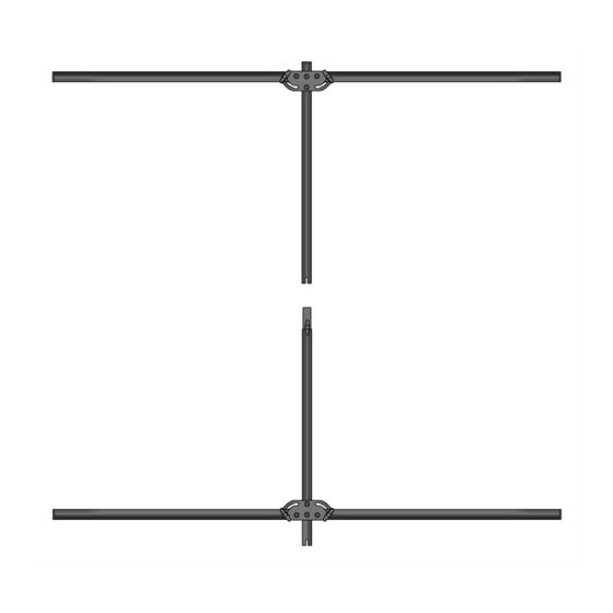
- Page 8 Antenna Center Section Insert the Center Section into the bottom of the antenna as shown. Once in place, hand-tighten the knobs in place to hold the bottom section securely. (This photo shows the manual tune center section). Antenna Top Section Unfold the two arms on the Antenna Top Section (DXE-TW-BAS-TOP) until they are perpendicular to the center tube as shown.
- Page 9 Control Cable and Control Console Attach the 65 foot control cable (DXE-TW-CCX) to the rear of the Remote Multi-Band Center Section as shown. Align the connector and push it on and tighten the collar clockwise. (Reverse it to remove the cable.) Run the control cable (and the coaxial cable) at a 45 degree angle from the rear of the antenna as shown.
-
Page 10: Fine Tuning
Coaxial Cable Connection Connect the suggested 75 feet of coaxial cable (DXE-8XDX075) to the SO-239 on the rear of the Remote Multi-Band Center Section as shown. Run the coaxial cable (and the control cable) at a 45 degree angle from the rear of the antenna as shown. - Page 11 You should try to spread or compress each of the two coils in a coil pair by the same amount. Warning: 1) Preparation. (Photos shown show the interior of the DXE-TW2010) To begin the tuning process, remove the center section switching array cover, and connect the control and coax cables to the switching array box, as described earlier in this manual.
-
Page 12: Guy Rope And Anchor Installation
Warranty All products manufactured by DX Engineering are warranted to be free from defects in material and workmanship for a period of one (1) year from date of shipment. DX Engineering’s sole obligation under these warranties shall be to issue credit, repair or replace any item or part thereof which is proved to be other than as warranted;...
Need help?
Do you have a question about the DXE-TW2010 and is the answer not in the manual?
Questions and answers