Table of Contents
Advertisement
Quick Links
Advertisement
Table of Contents

Related Manuals for DX Engineering RF-PRO-1B DXE-RF-PRO-1B


Summary of Contents for DX Engineering RF-PRO-1B DXE-RF-PRO-1B
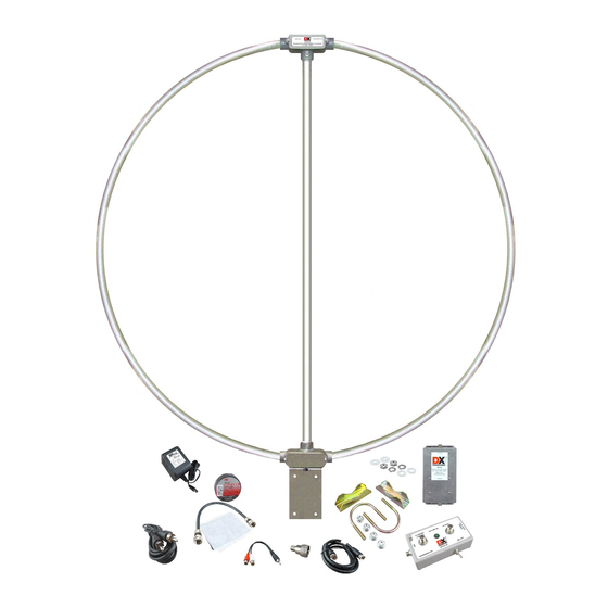
- Page 1 ® RF-PRO-1B Active Magnetic Loop Antenna DXE-RF-PRO-1B DXE-RF-PRO-1B-INS Revision 1 © DX Engineering 2020 1200 Southeast Ave. - Tallmadge, OH 44278 Phone: (800) 777-0703 ∙ Tech Support and International: (330) 572-3200 Fax: (330) 572-3279 ∙ E-mail: DXEngineering@DXEngineering.com...
-
Page 2: Antenna Design
75 ohm cable (RG-6 is recommended and is available from DX Engineering). For best results the antenna should be positioned a minimum of 15 feet away from any buildings or other sources of interference. The loop antenna may be rotated to take advantage of the directional properties of this type of antenna. - Page 3 the U.S. Air Force Research Laboratory and is the recipient of several awards from the IEEE (Institute of Electrical and Electronic Engineers) for his work. Developed for a classified U.S. Air Force project involving the measurement of EMP (Electro Magnetic Pulse) from nuclear weapons, this loop design has wide application to antennas for low- noise, interference-free radio reception over a wide frequency range.
-
Page 4: General Information
Caution: This is a Receive-Only Rotatable Antenna. Do not connect it to a transmitter as it will be damaged and void your warranty Do not inadvertently connect the (To Preamp) +20 VDC output of the power inserter to your receiver’s antenna input as your receiver may be damaged ... - Page 5 DX Engineering cannot be responsible for any damage that may result. Therefore, included in the loop’s power inserter is a relay “KEY” jack that can be actuated by the amplifier keying output of a typical transceiver.
- Page 6 The relay’s actuation circuit is designed to operate with a typical transceiver’s “KEY” signal. The power inserter has internal DIP switches that can be programmed to harmonize relay actuation with the proper state of the transceiver’s KEY signal. The default setting is such that when the KEY output is “low” (less than 0.7 VDC) the relay turns on and disconnects the preamplifier’s power and the connection to your receiver is grounded through a resistor.
- Page 7 TV antennas (A light duty rotator is available from DX Engineering). Ensure the antenna is mounted vertically and not leaning. There are weep holes in the Preamplifier box and these must be facing down to help eliminate any internal moisture build up.
-
Page 8: Overall Diagram
Overall Diagram This diagram shows the overall wiring scheme. Once familiar with this set up, assembling the antenna and making the actual cable connections is easy. Be extremely careful to avoid inadvertently connecting the 20 VDC antenna output of the power inserter to the antenna input on your receiver. - Page 9 Mounting the Preamplifier to the Loop Antenna L-Bracket The preamplifier is mounted to the L-bracket that is attached to the loop antenna using the included saddle clamp and mounting hardware which also connects the antenna to a short 1-1/4” diameter customer supplied mast (that would then normally go into the rotator).
- Page 10 Waterproofing F-Connectors & Weather Proofing The included one foot long RG-6 coaxial cable jumper is used to connect the output of the loop to the preamplifier. This cable uses specially designed F-connectors to eliminate moisture ingress. A package of coax seal and electrical tape is supplied for additional weatherproofing.
-
Page 11: Routine Maintenance
Every effort is made to supply the latest manual revision with each product. Occasionally a manual will be updated between the time your DX Engineering product is shipped and when you receive it. Please check the DX Engineering web site (www.dxengineering.com) for the latest revision manual. -
Page 12: Technical Support
All products manufactured by DX Engineering are warranted to be free from defects in material and workmanship for a period of one (1) year from date of shipment. DX Engineering’s sole obligation under these warranties shall be to issue credit, repair or replace any item or part thereof which is proved to be other than as warranted; no allowance shall be made for any labor charges of Buyer for replacement of parts, adjustment or repairs, or any other work, unless such charges are authorized in advance by DX Engineering.
Need help?
Do you have a question about the RF-PRO-1B DXE-RF-PRO-1B and is the answer not in the manual?
Questions and answers