
Related Manuals for ESD CPCI-ETH2


Summary of Contents for ESD CPCI-ETH2
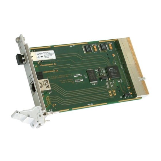
- Page 1 CPCI-ETH2 CPCI-ETH2-FX CPCI-ETH2-MX 10/100/1000BaseT- and/or 1000BASE-SX- ETHERNET Interface for CompactPCI Hardware Manual to Product I.2321.xx CPCI-ETH2 Hardware Manual Rev. 1.0...
- Page 2 The changes in the user’s manual listed below affect changes in the hardware as well as changes in the description of the facts only. Chapter Changes versus previous version First version Technical details are subject to change without notice. CPCI-ETH2 Hardware Manual Rev. 1.0...
- Page 3 gmbh.
-
Page 4: Table Of Contents
3. Front Panel View with LED-Display ..........10 3.1 CPCI-ETH2: LEDs and Connectors in the Front Panel ......10 3.2 CPCI-ETH2-MX: LEDs and Connectors in the Front Panel . - Page 5 This page is intentionally left blank. CPCI-ETH2 Hardware Manual Rev. 1.0...
-
Page 6: Overview
The interfaces for the fibre optic connections are suitable for 1000Base-SX-nets (1000Base-LX on request). The optical fibres are connected via LC-Duplex connectors in the front panel. LEDs in the front panel indicate the status of the CPCI-ETH2. CPCI-ETH2 Hardware Manual Rev. 1.0... -
Page 7: Summary Of Technical Data
X420 (8-pin RJ45-socket) - Ethernet Twisted Pair 10/100/1000BaseT, (CPCI-ETH2) U310 (HFBR-5911L/AL)- LC-Duplex connector 1000Base-SX, (CPCI-ETH2-FX) U410 (HFBR-5911L/AL)- LC-Duplex connector 1000Base-SX, (CPCI-ETH2-FX, CPCI-ETH2-MX) Dimensions 100 mm x 160 mm CPCI-ETH2: 165 g Weight CPCI-ETH2-MX: 170g CPCI-ETH2-FX: 175g CPCI-ETH2 Hardware Manual Rev. 1.0... -
Page 8: Compactpci Bus
Physical interface (1000Base-LX on request) 275 m at 62.5 m Multimode fibre Cable distance 550 m at 50 m Multimode fibre (10 km on request for 1000Base-LX) Connector LC-Duplex connector in the front panel CPCI-ETH2 Hardware Manual Rev. 1.0... -
Page 9: Software Support
Technical Data 1.2.5 Software Support The CPCI-ETH2-module operates with standard system drivers of Windows NT/2000, Linux, VxWorks and QNX. CPCI-ETH2 Hardware Manual Rev. 1.0... -
Page 10: Order Information
Contents: Circuit diagrams, PCB top overlay drawing, I.2321.25 data sheets of significant components 1*) If module and manual are ordered together, the manual is free of charge. 2*) This manual is liable for costs, please contact our support. CPCI-ETH2 Hardware Manual Rev. 1.0... -
Page 11: Hardware Installation
Disconnect the computer from mains. Insert the CPCI-ETH2 module into a free CompactPCI bus slot. Fix the CPCI-ETH2-module with the mounting screws in the front panel. Connect the Ethernet cables (10/100/1000Base-T) to the RJ45-sockets (X320, X420) or if applicable the Multimode fibre optic cables (1000Base-SX) to the LC-Duplex connectors (U310, U410) in the front panels. - Page 12 Connect the computer to mains again. Switch on the computer and the peripheral devices. End of hardware installation. 10. Now, you can install the Gigabit Ethernet interface. Refer to the documentation of your operating system. CPCI-ETH2 Hardware Manual Rev. 1.0...
-
Page 13: Front Panel View With Led-Display
Front panel view with LED-Display 3. Front Panel View with LED-Display 3.1 CPCI-ETH2: LEDs and Connectors in the Front Panel Fig. 3.1.1: Position of the LEDs and connectors of the CPCI-ETH2 Color Name Indication of the LED (LED on) Link Status-Ethernet 2 (10/100/1000BaseT) -
Page 14: Cpci-Eth2-Mx: Leds And Connectors In The Front Panel
Front panel view with LED-Display 3.2 CPCI-ETH2-MX: LEDs and Connectors in the Front Panel Fig. 3.2.1: Position of the LEDs and connectors of the CPCI-ETH2-MX Color Name Indication of the LED (LED on) Link Status Ethernet LWL2 (1000BASE-SX) LED400A green... -
Page 15: Cpci-Eth2-Fx: Leds And Connectors In The Front Panel
Front panel view with LED-Display 3.3 CPCI-ETH2-FX: LEDs and Connectors in the Front Panel Fig. 3.3.1: Position of the LEDs and connectors of the CPCI-ETH2-FX Color Name Indication of the LED (LED on) Link Status Ethernet LWL 2 (1000BASE-SX) LED400A... -
Page 16: Control
Connector Assignment 4. Control The CPCI-ETH2 module operates with the standard system drivers of Windows 95/98, Windows NT/2000, Linux, VxWorks and QNX. For software installation, please refer to the manual of the operating system. 5. Connector Assignment 5.1 Ethernet 10/100/1000BaseT-Connection (X320, X420) -
Page 17: Ethernet 1000Base-Sx Connector (U310, U410)
Connector type: LC-Duplex connector, integrated in HFBR-5911L/AL Warning! The fibre optic interfaces are equipped with class 1 laser products. Avoid direct eye exposure to the beam coming from the transmit port. Fibre Position: Assignment: Fibre Signal LC-Duplex connector CPCI-ETH2 Hardware Manual Rev. 1.0...
Need help?
Do you have a question about the CPCI-ETH2 and is the answer not in the manual?
Questions and answers