Table of Contents
Advertisement
Quick Links
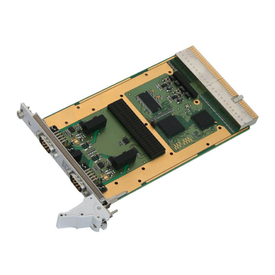
CPCI-CAN/400-2
2 CAN Interfaces with ARINC825 Option
and optional PXI-Interface
Hardware Manual
to Product C.2033.02
CPCI-CAN/400-2
Hardware Manual • Doc. No.: C.2033.23 / Rev. 1.2
Page 1 of 26
esd electronic system design gmbh
Vahrenwalder Str. 207 • 30165 Hannover • Germany
http://www.esd.eu
Phone: +49 (0) 511 3 72 98-0 • Fax: +49 (0) 511 3 72 98-68
Advertisement
Table of Contents

Subscribe to Our Youtube Channel
Related Manuals for ESD CPCI-CAN/400-2


Summary of Contents for ESD CPCI-CAN/400-2
- Page 1 CPCI-CAN/400-2 Hardware Manual • Doc. No.: C.2033.23 / Rev. 1.2 Page 1 of 26 esd electronic system design gmbh Vahrenwalder Str. 207 • 30165 Hannover • Germany http://www.esd.eu Phone: +49 (0) 511 3 72 98-0 • Fax: +49 (0) 511 3 72 98-68...
- Page 2 The information in this document has been carefully checked and is believed to be entirely reliable. esd makes no warranty of any kind with regard to the material in this document, and assumes no responsibility for any errors that may appear in this document. In particular descriptions and technical data specified in this document may not be constituted to be guaranteed product features in any legal sense.
- Page 3 Absolute maximum power and description of additional front panel added. 2015-12-10 OnTime RTOS-32 and J1939 protocol libraries added Declaration of Conformity updated Order Information added Technical details are subject to change without further notice. CPCI-CAN/400-2 Hardware Manual • Doc. No.: C.2033.23 / Rev. 1.2 Page 3 of 26...
- Page 4 ● Do not operate the CPCI-CAN/400-2 adjacent to heat sources and do not expose it to unnecessary thermal radiation. Ensure an ambient temperature as specified in the technical data. ● Do not use damaged or defective cables to connect the CPCI-CAN/400-2 and follow the CAN wiring hints in chapter: "Correctly Wiring Electrically Isolated CAN Networks".
-
Page 5: Table Of Contents
8.1 Termination.......................... 22 Electrical Grounding......................23 Short Circuit in CAN Wiring....................23 CAN_H/CAN_L-Voltage ......................23 CAN Transceiver Resistance Test..................24 Support by esd........................24 Declaration of Conformity......................25 Order Information........................26 CPCI-CAN/400-2 Hardware Manual • Doc. No.: C.2033.23 / Rev. 1.2 Page 5 of 26... -
Page 6: Overview
The CPCI-CAN/400-2 is a CompactPCI ® board in 3U format, that features two electrically isolated high-speed CAN interfaces according to ISO 11898-2. CAN is driven by the esd Advanced CAN Core (esdACC) CAN controller implemented in the Xilinx ® Spartan ®... -
Page 7: Pcb View With Connectors
The jumper (JP600A) has to be left in delivery status! Otherwise the software driver can not be started. See also page 14 for signal assignment of the CAN connectors. CPCI-CAN/400-2 Hardware Manual • Doc. No.: C.2033.23 / Rev. 1.2 Page 7 of 26... -
Page 8: Hardware Installation
Connect the CAN interfaces via the DSUB9 connectors in the front panel of the CPCI- CAN/400-2 (see page 7). Please note that the CAN bus has to be terminated at both ends! esd offers special T- connectors and termination connectors. Additionally the CAN_GND signal has to be connected to earth at exactly one point in the CAN network. - Page 9 Hardware Installation Connect the computer to mains again (mains connector or safety fuse). 10. Switch on the computer and the peripheral devices. 11. End of hardware installation. CPCI-CAN/400-2 Hardware Manual • Doc. No.: C.2033.23 / Rev. 1.2 Page 9 of 26...
-
Page 10: Leds
LED name Colour Function Description in schematic State diagram CPCI-CAN/400-2 not ready, FPGA is not loaded green Power LED500D CPCI-CAN/400-2 is operational, FPGA is loaded no error detected on CAN0 or CAN1 green error occurred on CAN net 0 and /or net 1... -
Page 11: Technical Data
Weight 190 g Table 2: General data of the module 5.2 Microprocessor and Memory BlockRAM (FPGA) 72 KB DRAM 64 MB Table 3: Microprocessor and Memory CPCI-CAN/400-2 Hardware Manual • Doc. No.: C.2033.23 / Rev. 1.2 Page 11 of 26... -
Page 12: Can Interface
32-bit µC in FPGA (MicroBlaze) Board dimension according to CompactPCI Specification, Rev. 2.2 Connector Universal-Board, not keyed Connector coding (3.3 V or 5 V signalling voltage) Page 12 of 26 Hardware Manual • Doc. No.: C.2033.23 / Rev. 1.2 CPCI-CAN/400-2... -
Page 13: Software Support
J1939 protocol libraries are available for Windows, others on request. For detailed information about the driver availability for your special operating system please contact our sales team. CPCI-CAN/400-2 Hardware Manual • Doc. No.: C.2033.23 / Rev. 1.2 Page 13 of 26... -
Page 14: Connector Assignments
CAN physical layer of CANX (X ... 0,1) Shield ... shielding (connected with the case of the 9-pin DSUB connector) reserved ... reserved for future applications, do not connect! Page 14 of 26 Hardware Manual • Doc. No.: C.2033.23 / Rev. 1.2 CPCI-CAN/400-2... -
Page 15: Correctly Wiring Electrically Isolated Can Networks
Therefore the practical maximum number of nodes, bus length and stub length are typically much lower. esd has concentrated her recommendations concerning CAN wiring on the specifications of the ISO 11898-2. Thus this wiring hints forgoes to describe the special features of the derived standards CANopen, ARINC825, DeviceNet and NMEA2000. -
Page 16: Heavy Industrial Environment (Double Twisted Pair Cable)
7.2 Heavy Industrial Environment (Double Twisted Pair Cable) 7.2.1 General Rules NOTICE esd only grants the compliance with directive 2014/30/EU, if the CAN wiring is carried out with single shielded double twisted pair cables that match the requirements of ISO 11898-2. -
Page 17: Device Cabling
DSUB9 connector from ERNI (ERBIC CAN BUS MAX, order no.:154039). The usage of esd’s T-connector type C.1311.03 is not recommended for single shielded double twisted pair cables because the shield potential of the conductive DSUB housing is not looped through this T-connector type. -
Page 18: Light Industrial Environment (Single Twisted Pair Cable)
7.3.1 General Rules NOTICE esd only grants the compliance with directive 2014/30/EU, if the CAN wiring is carried out with single shielded double twisted pair cables that match the requirements of ISO 11898-2. See previous chapter: 'Heavy Industrial Environment (Double Twisted Pair Cable)'. -
Page 19: Cabling
9-pin DSUB-termination connectors with integrated termination resistor and male and ● female contacts (gender changer) are available from esd (order no. C.1303.01). DSUB termination connectors with male contacts (order no. C.1302.01) or female contacts ● (order no. C.1301.01) and additional functional earth contact are available, if CAN termination and grounding of CAN_GND is required. -
Page 20: Electrical Grounding
5000 Table 5: Recommended cable lengths at typical bit rates (with esd-CAN interfaces) Optical couplers are delaying the CAN signals. esd modules typically reach a wire length of ● 37 m at 1 Mbit/s within a proper terminated CAN network without impedance disturbances like e.g. -
Page 21: Examples For Can Cables
Correctly Wiring Electrically Isolated CAN Networks 7.6 Examples for CAN Cables esd recommends the following two-wire and four-wire cable types for CAN network design. These cable types are used by esd for ready-made CAN cables, too. 7.6.1 Cable for light industrial Environment Applications (Two-Wire) -
Page 22: Can Troubleshooting Guide
- there are no open circuits in CAN_H or CAN_L wiring - your bus system has two terminating resistors (one at each end) and that they are 120 Ω each. Page 22 of 26 Hardware Manual • Doc. No.: C.2033.23 / Rev. 1.2 CPCI-CAN/400-2... -
Page 23: Electrical Grounding
(see figure at previous page). 4. Measure the DC voltage between CAN_L and CAN_GND (see figure at previous page). Normally the voltage should be between 2.0 V and 3.0 V. CPCI-CAN/400-2 Hardware Manual • Doc. No.: C.2033.23 / Rev. 1.2 Page 23 of 26... -
Page 24: Can Transceiver Resistance Test
If you have executed the fault diagnostic steps of this troubleshooting guide and you even can not find a solution for your problem our support department will be able to assist. Please contact our support via email at support@esd.eu or by phone +40-511-37298-130. Page 24 of 26 Hardware Manual •... -
Page 25: Declaration Of Conformity
Declaration of Conformity 9. Declaration of Conformity CPCI-CAN/400-2 Hardware Manual • Doc. No.: C.2033.23 / Rev. 1.2 Page 25 of 26... -
Page 26: Order Information
For detailed information about the driver availability for your special operating system, please contact our sales team. Table 6: Order information PDF Manuals For availability of English manuals see table below. Please download the manuals as PDF documents from our esd website www.esd.eu for free. Manuals Order No.
Need help?
Do you have a question about the CPCI-CAN/400-2 and is the answer not in the manual?
Questions and answers