Table of Contents
Advertisement
Quick Links
Advertisement
Table of Contents

Subscribe to Our Youtube Channel
Related Manuals for Vaisala WMS302


Summary of Contents for Vaisala WMS302
- Page 1 Combined Wind Sensor WMS301 and WMS302 UIDE M210375en-A December 2002...
- Page 2 The contents are subject to change without prior notice. Please observe that this manual does not create any legally binding obligations for Vaisala towards the customer or end user. All legally binding commitments and agreements are included exclusively in the...
-
Page 3: Table Of Contents
___________________________________________________________________ Table of Contents CHAPTER 1 GENERAL INFORMATION ............3 About This Manual..........3 Contents of This Manual........3 Version Information..........4 Feedback..............4 Safety ...............4 General Safety Considerations......4 Product Related Safety Precautions .....5 ESD Protection .............5 Regulatory Compliances........6 Warranty ..............6 CHAPTER 2 PRODUCT OVERVIEW.............7 Introduction to WMS Series Wind Sensors ..7 Product Nomenclature ...........9 CHAPTER 3... - Page 4 Alignment Sleeve) ..........15 Figure 9 Mounting of the Combined Wind Sensor....16 Figure 10 WMS301/WMS302 Installation with WMS30KIT ..18 Figure 11 Aligning the Combined Wind Sensor...... 19 Figure 12 WMS Assembly ............23 Figure 13 Dimensions (in mm) of the Combined Wind Sensor..............
-
Page 5: Chapter 1 General Information
GENERAL INFORMATION This chapter provides general notes for the product. About This Manual This manual provides information for installing, maintaining, and troubleshooting WMS301 and WMS302 Combined Wind Sensor. Contents of This Manual This manual consists of the following chapters: - Chapter 1, General Information, provides general notes for the product. -
Page 6: Version Information
User's Guide ________________________________________________________ - Chapter 6, Technical Data, provides the technical data of WMS301 and WMS302 Combined Wind Sensor. Version Information Table 1 Manual Revisions Manual Code Description M010030en-C WMS301 & WMS302 Combined Wind Sensors Quick Reference Guide M210375en-A First version of the WMS301 and WMS302 Combined Wind Sensor User's Guide. -
Page 7: Product Related Safety Precautions
ESD Protection Electrostatic Discharge (ESD) can cause immediate or latent damage to electronic circuits. Vaisala products are adequately protected against ESD for their intended use. However, it is possible to damage the product by delivering electrostatic discharges when touching, removing, or inserting any objects inside the equipment housing. -
Page 8: Regulatory Compliances
- Always hold the boards by the edges and avoid touching the component contacts. Regulatory Compliances The WMS301 and WMS302 sensors comply with the following performance and environmental test standards: - Mechanical vibration test per 1EC-68-2-6 Fc - RF field emission test per EN 55022 Class B... -
Page 9: Chapter 2 Product Overview
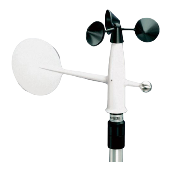
Chapter 2 ____________________________________________ Product Overview CHAPTER 2 PRODUCT OVERVIEW This chapter introduces the WMS301 and WMS302 Combined Wind Sensor features. Introduction to WMS Series Wind Sensors WMS series wind sensors are compact sized instruments with the wind speed and direction sensors integrated into one unit. -
Page 10: Figure 1 Wms Series Combined Wind Sensor
User's Guide ________________________________________________________ averaging of transient intervals should be used, since two pulses with non-symmetric positioning are generated during one revolution. The balanced wind vane is integrated in the housing, underneath the cup wheel. The circular tail is located far enough from the body and the cup wheel to avoid turbulence due to these structures. -
Page 11: Product Nomenclature
Chapter 2 ____________________________________________ Product Overview WMS302 has a two-wiper type potentiometer to overcome the wind direction discontinuity. However, a more complex voltage-to-direction conversion process is needed. Product Nomenclature Table 2 WMS Series Wind Sensor Nomenclature Code Common Name Basic WMS301... - Page 12 User's Guide ________________________________________________________ This page intentionally left blank. 10 _____________________________________________________ M210375en-A...
-
Page 13: Chapter 3 Installation
Chapter 3 __________________________________________________ Installation CHAPTER 3 INSTALLATION This chapter provides you with information that is intended to help you install the wind sensor. Selecting Location Allow sufficient clearance for the wind sensor. Install the wind sensor away from buildings or any other objects that might affect the airflow. -
Page 14: Connector
Connector The WMS301 connector is shown in Figure 4 on page 13. The WMS302 connector is shown in Figure 5 on page 13. Type M12 female connector, for example, made by Lumberg, Phoenix, or Binder is suitable for connecting the cable to the sensor. -
Page 15: Figure 4 Wms301 Connector
4 = GND, ground 5 = SPD, signal output, wind speed 0212-223 Figure 5 WMS302 Connector The following numbers refer to Figure 5 above. 1 = +Vref, voltage input 2 = DIR1, signal output, wind direction 3 = GND, ground... -
Page 16: Installation Procedure
For measuring the direction, note that 10 kΩ/360º and 10 kΩ/180° potentiometers are used with WMS301 and WMS302 respectively. For the principal circuit diagrams, refer to Figure 6 below and Figure 7 on page 15. 0212-224... -
Page 17: Figure 7 Wms302 Principal Circuit Diagram
0212-225 Figure 7 WMS302 Principal Circuit Diagram The WMS302 sensor is aligned at the factory according to Figure 8 below. This factory alignment applies to all models with the alignment sleeve. The alignment sleeve is secured with a small size Allen bolt to the sensor body. -
Page 18: Mounting
User's Guide ________________________________________________________ Mounting Mounting Sensor to the Wind Sensor Mast After a proper location for wind measurement has been selected, you can mount the sensor to the wind sensor mast. The diameter of the wind sensor mast is 30 mm. To mount the sensor, do the following: Fit the cable (number 2 in Figure 9 below) through the mounting piece (3) and connect the cable to the sensor. -
Page 19: Mounting To A Pole Mast With Wms30Kit
Chapter 3 __________________________________________________ Installation Secure the mounting piece (3) to the mast by tightening the mounting screw (6). Route the sensor cable down along the mast and always attach the cable to the mast with cable ties. Mount the wind sensor mast firmly to a solid base, for example, to a pole mast. -
Page 20: Figure 10 Wms301/Wms302 Installation With Wms30Kit
User's Guide ________________________________________________________ 0103-010 Figure 10 WMS301/WMS302 Installation with WMS30KIT The following numbers refer to Figure 10 above: 1 = WMS301 or WMS302 2 = Wood screws 3 = Cable tie 4 = Wooden mast 5 = Plastic protective plate... -
Page 21: Aligning The Sensor
Chapter 3 __________________________________________________ Installation To mount the wind sensor mast to a wooden mast, do the following (the numbers refer to Figure 10 on page 18): Attach the mounting piece with the wood screws (2) to the wooden mast (4) through the wind sensor mast. Secure the cable with the fixed cable tie (3) to the wind sensor mast. - Page 22 User's Guide ________________________________________________________ Choose a known wind direction reference point on the horizon with the help of a compass. Point the nose (1) of the vane at the reference point. Hold the vane in position and slowly rotate the mounting piece (4) until wind direction shows proper value.
-
Page 23: Chapter 4 Maintenance
Chapter 4 ________________________________________________ Maintenance CHAPTER 4 MAINTENANCE This chapter provides information that is needed in basic maintenance of the product. Periodic Maintenance Testing Proper Operation It is recommended to check the ball bearings of the anemometer and the vane every year. If the cup wheel or the vane is not rotating smoothly or it creates detectable noise, the bearings must be replaced. - Page 24 User's Guide ________________________________________________________ To replace the ball bearings, do the following (the numbers refer to Figure 12 on page 23): Anemometer bearings: Loosen the hubnut (14) with fingers or a 10 mm tool and remove the cup wheel (13). Remove the ball bearing assembly (12) by unscrewing it counterclockwise (with a 10 mm tool).
-
Page 25: Figure 12 Wms Assembly
Chapter 4 ________________________________________________ Maintenance 10 = Tail assembly 11 = Lock screw 12 = Bearing assembly 13 = Cup wheel 14 = Hubnut 0009-022 Figure 12 WMS Assembly VAISALA__________________________________________________________23... -
Page 26: Parts List For Consumables
User's Guide ________________________________________________________ Parts List for Consumables Table 3 Available Spare Parts Spare Part Order Code Cup wheel assembly WA45233 Anemometer bearing assembly WA45232 Vane assembly WA35234 Set of bearings 25160WA 24 _____________________________________________________ M210375en-A... -
Page 27: Chapter 5 Troubleshooting
The sensor is not powered Check that the supply voltage properly. is 3 to 15 VDC Technical Support For technical questions, contact the Vaisala technical support: E-mail helpdesk@vaisala.com Telephone +358 9 8949 2789 +358 9 8949 2790 VAISALA__________________________________________________________25... -
Page 28: Return Instructions
Pack the faulty product using an ESD protection bag of good quality with proper cushioning material in a strong box of adequate size. Please include the Problem Report in the same box. Send the box to: Vaisala Oyj SSD Service Vanha Nurmijärventie 21 FIN-01670 Vantaa Finland... -
Page 29: Chapter 6 Technical Data
Chapter 6 _______________________________________________Technical Data CHAPTER 6 TECHNICAL DATA This chapter provides the technical data of WMS301 and WMS302 Combined Wind Sensor. Specifications Table 5 Anemometer Specifications Property Description/Value Sensor / Transducer type Dual Reed switch Measuring range 0.5 ... 60 m/s Starting threshold <... -
Page 30: Table 6 Vane Specifications
User's Guide ________________________________________________________ Table 6 Vane Specifications Property Description/Value Sensor / Transducer type Potentiometer Measuring range WMS302 0 ... 360° WMS301 0 ... 355° Starting threshold < 1.0 m/s Damping ratio Overshoot ratio Delay distance 0.6 m Accuracy Better than ± 3°... -
Page 31: Dimensions
Chapter 6 _______________________________________________Technical Data Dimensions 0212-228 Figure 13 Dimensions (in mm) of the Combined Wind Sensor MTBF The calculated mean time between failure is 4.4 × 10 h for permanent installations. The value equals to 2.27 when expressed in a failure frequency during 10 hours of use.
Need help?
Do you have a question about the WMS302 and is the answer not in the manual?
Questions and answers