
Related Manuals for FLIR Raymarine CAM220IP


Summary of Contents for FLIR Raymarine CAM220IP
- Page 1 CAM220IP INSTALLATION INSTRUCTIONS English (EN) Date: 04-2016 Document number: 87268-1 © 2016 Raymarine UK Limited...
- Page 3 Gear Up, Marine Shield, Seahawk, Autohelm, Automagic, and Visionality are registered or claimed trademarks of Raymarine Belgium. FLIR, DownVision, SideVision, Dragonfly, Instalert, Infrared Everywhere, and The World’s Sixth Sense are registered or claimed trademarks of FLIR Systems, Inc. All other trademarks, trade names, or company names referenced herein are used for identification only and are the property of their respective owners.
-
Page 5: Table Of Contents
Contents Chapter 1 Important information......7 8.4 Resetting the camera ........... 42 Certified Installation ........... 7 Chapter 9 Technical support ......43 Power Over Ethernet (PoE) ........7 9.1 Raymarine product support and servicing ....44 Water ingress ............7 Chapter 10 Technical specification.... - Page 6 CAM220IP...
-
Page 7: Chapter 1 Important Information
Chapter 1: Important information Warning: Ensure all equipment has isolated power supply This product features an isolated power Certified Installation supply. To prevent potential damage to Raymarine recommends certified installation by a equipment, Raymarine recommends that Raymarine approved installer. A certified installation any external equipment connected to this product also features an isolated power qualifies for enhanced product warranty benefits. -
Page 8: Disclaimer
Disclaimer correct EMC performance. If ferrites are supplied separately to the cables (i.e. not pre-fitted), you Raymarine does not warrant that this product is must fit the supplied ferrites, using the supplied error-free or that it is compatible with products instructions. -
Page 9: Imo And Solas
IMO and SOLAS The equipment described within this document is intended for use on leisure marine boats and workboats NOT covered by International Maritime Organization (IMO) and Safety of Life at Sea (SOLAS) Carriage Regulations. Technical accuracy To the best of our knowledge, the information in this document was correct at the time it was produced. - Page 10 CAM220IP...
-
Page 11: Chapter 2 Document And Product Information
Chapter 2: Document and product information Chapter contents • 2.1 Document information on page 12 • 2.2 Product overview on page 12 Document and product information... -
Page 12: Document Information
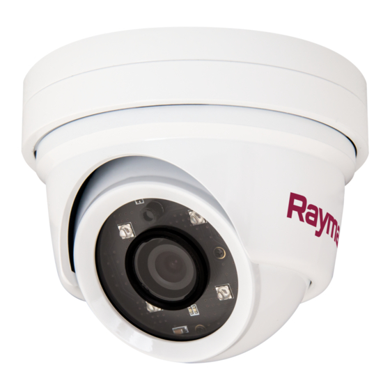
2.1 Document information 2.2 Product overview This document contains important information CAM220IP related to the installation of your Raymarine product. The CAM220IP is an Infrared illuminated (I ) eyeball The document includes information to help you: IP camera with both day and night vision. In conjunction with a compatible multifunction display •... -
Page 13: Chapter 3 Planning The Installation
Chapter 3: Planning the installation Chapter contents • 3.1 Installation checklist on page 14 • 3.2 Compatible multifunction displays on page 14 • 3.3 Parts supplied on page 15 • 3.4 Tools required on page 15 • 3.5 Typical systems on page 16 •... -
Page 14: Installation Checklist
3.1 Installation checklist 3.2 Compatible multifunction displays Installation includes the following activities: This product is compatible with the following LightHouse powered Raymarine multifunction Installation Task displays. Plan your system. • a Series, c Series, e Series, eS Series. Obtain all required equipment and tools. •... -
Page 15: Parts Supplied
3.3 Parts supplied 3.4 Tools required Product installation requires the following tools: CAM220IP Item Description The following items are supplied with your product. Power drill Item Description Quantity IP camera (Includes a 1 m (39.4 in) ethernet and power pigtail cable) Documentation and software pack Drill bit of appropriate size*... -
Page 16: Typical Systems
3.5 Typical systems 3.6 Warnings and cautions Note: For information on how to connect the Important: Before proceeding, ensure that you product, refer to the Chapter 4 Cables and have read and understood the warnings and connections section. For information on available cautions provided in the Chapter 1 Important cables and accessories, refer to the... -
Page 17: General Location Requirements
3.7 General location requirements 3.8 Camera orientation Important considerations when choosing a suitable The camera can be mounted in 2 orientations location for your product. referred to as “Ball up” and “Ball down”. This product is suitable for mounting below decks. The default image orientation is for the ball-down configuration, if the camera is to be mounted in the The product should be mounted where it will be:... -
Page 18: Product Dimensions
3.9 Product dimensions CAM220IP 99.2 mm (3.91 in) D12985-1 CAM220IP... -
Page 19: Chapter 4 Cables And Connections
Chapter 4: Cables and connections Chapter contents • 4.1 General cabling guidance on page 20 • 4.2 Connections overview on page 21 • 4.3 Power options on page 21 • 4.4 Power connection on page 22 • 4.5 Network connection on page 24 Cables and connections... -
Page 20: General Cabling Guidance
4.1 General cabling guidance • Always use an RS232/NMEA converter with optical isolation on the signal lines. Cable types and length • Always make sure that PC’s or other sensitive electronic devices have a dedicated power circuit. It is important to use cables of the appropriate type and length Cable shielding •... -
Page 21: Connections Overview
• Multifunc- to SeaTalk tion display • Connection to a suitably-powered Raymarine adaptor cable or FLIR PoE injector. Only one cable is • PC is required. required to carry both data and power signals Refer to between the camera and the PoE injector. -
Page 22: Power Connection
4.4 Power connection Self-powered The unit can be powered from a 12 volt dc power supply using its dedicated power cable. 12 v dc Note: The power cable is supplied with a terminator fitted, this must be removed if the device is to be self-powered. - Page 23 2-wire cable from the unit to the vessel's battery or distribution panel. • Raymarine recommends a minimum wire gauge of 18AWG (0.82 mm ) for any length of cable extension. • For all lengths of extension to the power cable, ensure there is a continuous minimum voltage at the product’s power connector of 10.8 V with a fully flat battery at 11 V.
-
Page 24: Network Connection
4.5 Network connection Grounding Ensure that you observe the separate grounding The unit must be connected to a compatible MFD or advice provided in the product’s documentation. PC to enable the video feed to be viewed. More information PC connection Raymarine recommends that best practice is When connecting the camera directly to a PC observed in all vessel electrical installations, as... - Page 25 Item Description Waterproof RJ45 ethernet coupler (R32142) (supplied) Camera’s ethernet cable Camera’s power cable (Connection not required if the camera is being supplied PoE by the MFD.) Note: The connection panel on your product may look slightly different to that shown, depending on variant.
- Page 26 CAM220IP...
-
Page 27: Chapter 5 Mounting
Chapter 5: Mounting Chapter contents • 5.1 Mounting the unit on page 28 Mounting... -
Page 28: Mounting The Unit
5.1 Mounting the unit counter-clockwise, then pull the base away from the camera body. Having chosen a suitable location, install the unit as follows: Ensure the power supply is switched off and that the necessary cables have been fed to the mounting location. - Page 29 14. To attach the external plastic collar to the camera base, align the three lugs with the slots in the base, then turn the collar clockwise to lock it into position around the ball. D13531-1 Note: If the collar is blocking the camera’s field of view, remove it, and reposition the ball as required.
- Page 30 CAM220IP...
-
Page 31: Chapter 6 Operation
Chapter 6: Operation Chapter contents • 6.1 Operation instructions on page 32 • 6.2 Web browser interface on page 32 • 6.3 Reverse video and video flip on page 35 • 6.4 Resetting the camera to factory defaults on page 35 Operation... -
Page 32: Operation Instructions
6.1 Operation instructions 6.2 Web browser interface For detailed operation instructions for your product, Network setup and operation refer to the documentation that accompanies your display. Default username, password and ports Username admin Password 1234 Ports • 80 (HTTP) • 554 (RTSP) •... - Page 33 7. Place a tick in the box for the type of network that the camera is on (this is usually Public). 8. Click OK. 9. From the Control Panel click Network and 2. Double-click a camera icon to open the web Internet.
- Page 34 Internet Explorer - ActiveX and Flash Player • Mozilla Firefox • Apple Safari The ActiveX plug-in may provide smoother video performance than Flash Player. • Microsoft Internet Explorer 7.0 or later, 32–bit 1. If your computer has Flash Player installed: version (using ActiveX) i.
-
Page 35: Reverse Video And Video Flip
6.3 Reverse video and video flip 6.4 Resetting the camera to factory defaults The video feed can be reversed (mirror image), flipped upside down or reversed and flipped Follow the steps below to reset your camera’s depending on your installation. settings to their factory default values. - Page 36 CAM220IP...
-
Page 37: Chapter 7 Maintenance
Chapter 7: Maintenance Chapter contents • 7.1 Routine checks on page 38 • 7.2 Unit cleaning instructions on page 38 Maintenance... -
Page 38: Routine Checks
7.1 Routine checks 7.2 Unit cleaning instructions The following periodic checks should be made: The unit does not require regular cleaning. However, if you find it necessary to clean the unit, please follow • Examine cables for signs of damage, such as the steps below: chafing, cuts or nicks. -
Page 39: Chapter 8 System Checks And Troubleshooting
Chapter 8: System checks and troubleshooting Chapter contents • 8.1 Troubleshooting on page 40 • 8.2 LED status on page 40 • 8.3 IP camera troubleshooting on page 41 • 8.4 Resetting the camera on page 42 System checks and troubleshooting... -
Page 40: Troubleshooting
8.1 Troubleshooting 8.2 LED status The troubleshooting information provides possible The unit has an LED status indicator to help causes and corrective action required for common determine the camera’s state. problems associated with marine electronics LED sequence LED color State installations. -
Page 41: Ip Camera Troubleshooting
8.3 IP camera troubleshooting Problem Possible Solutions Camera does not power on. Power over Ethernet (PoE) connection • Ensure that the ethernet cable is connected correctly and that connections are secure. • Ensure you are not using a crossover coupler or cable as they are not appropriate for PoE applications. -
Page 42: Resetting The Camera
8.4 Resetting the camera When connected to an MFD it should not be necessary to perform a factory reset. However in the event that a factory reset is required the camera’s built-in web interface must be used. The camera’s web interface can be accessed when connected to a web-enabled device such as a PC. -
Page 43: Chapter 9 Technical Support
Chapter 9: Technical support Chapter contents • 9.1 Raymarine product support and servicing on page 44 Technical support... -
Page 44: Raymarine Product Support And Servicing
246 932 164 64 (Raymarine subsidiary) Asia Pacific Russia +7 495 info@mikstmarine.ru United States +1 (603) rm-usrepair@flir.com 788 0508 (Authorized Raymarine (US) 324 7900 distributor) Web support Please visit the “Support” area of the Raymarine website for: • Manuals and Documents —... -
Page 45: Chapter 10 Technical Specification
Chapter 10: Technical specification Chapter contents • 10.1 Technical specification on page 46 Technical specification... -
Page 46: Technical Specification
10.1 Technical specification Video streaming Supports multi streaming with H.264, MJPEG Physical specification Frame Rate • H.264: 30fps @ 1920 x Dimensions • Base diameter: 99.2 mm 1080p (3.9 in) • MJPEG: 30fps @ VGA • Overall Height: 80.7 mm resolution (3.2 in) Bit Rate Control... -
Page 47: Chapter 11 Spares And Accessories
Chapter 11: Spares and accessories Chapter contents • 11.1 Network hardware on page 48 • 11.2 RayNet to RJ45 adapter cables on page 49 • 11.3 Network cable connector types on page 50 • 11.4 RayNet to RayNet cables and connectors on page 51 Spares and accessories... -
Page 48: Network Hardware
11.1 Network hardware Part num- Item Notes HS5 RayNet A80007 5–port switch for network network switch connection of multiple devices featuring RayNet connectors. Equipment with RJ45 SeaTalk connectors can also be connected using suitable adapter cables. RJ45 SeaTalk E55058 8–port switch for network network switch connection of multiple SeaTalk... -
Page 49: Raynet To Rj45 Adapter Cables
11.2 RayNet to RJ45 adapter cables 400 mm (1.3 ft) A80160 100 mm (3.9 in) A80247 400 mm (1.3 ft) A80272 3 m (9.84 ft) A80276 1 m (3.28 ft) 3 m (9.84 ft) 10 m (32.8 ft) A62360 A80151 A80159 D13158-1 Description... -
Page 50: Network Cable Connector Types
11.3 Network cable connector types There are 2 types of network cable connector — RayNet, and RJ45 SeaTalk RJ45 SeaTalk connector. RayNet connector. CAM220IP... -
Page 51: Raynet To Raynet Cables And Connectors
11.4 RayNet to RayNet cables and connectors 400 mm (1.3 ft) 2 m (6.56 ft) 5 m (16.4 ft) 10 m (32.8 ft) 20 m (65.6 ft) A80161 A62361 A80005 A62362 A80006 R70014 A80262 100 mm (3.9 in) A80162 D13160-1 Description Typical use Quantity... - Page 52 CAM220IP...
- Page 54 www.raymarine.com Raymarine UK Limited, Marine House, Cartwright Drive, Fareham, PO15 5RJ. United Kingdom. Tel: +44 (0)1329 246 700...
Need help?
Do you have a question about the Raymarine CAM220IP and is the answer not in the manual?
Questions and answers