
Related Manuals for Rosslare AYC-E/Q60 Series


Summary of Contents for Rosslare AYC-E/Q60 Series
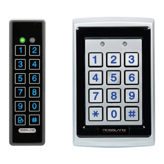
- Page 1 2012 March AYC-E/Q60 Family Vandal Resistant Convertible Reader/Controllers Instruction Manual...
- Page 2 ROSSLARE. ROSSLARE reserves the right to revise and change this document at any time, without being obliged to announce such revisions or changes beforehand or after the fact.
-
Page 3: Table Of Contents
5.2.4 Keypad Transmission Format Option Number ......25 5.2.5 Selecting HID Prox Card Transmission Format ......30 5.2.6 Selecting Rosslare PROX Card Transmission Format ....30 5.2.7 Changing the Programming Code ..........33 5.2.8 Changing the Facility Code ............33 5.2.9... - Page 4 Table of Contents 5.2.10 Setting the Reader Format ............35 5.2.11 Return to Factory Default Settings ..........35 5.2.12 Replacing a Lost Programming Code ......... 36 Controller Functionality.......... 37 Normal, Secure, and Master Users ........37 Modes of Operation ............38 6.2.1 Normal Mode ................
- Page 5 Setting the Lockout Feature ............56 6.10.12 Setting the Backlight Behavior ........... 57 6.10.13 Selecting the Rosslare PROX and HID Prox Format ..... 57 6.10.14 Enrolling Primary and Secondary Codes ........58 6.10.15 Deleting Primary and Secondary Codes ........62 6.10.16...
- Page 6 List of Figures List of Figures Figure 1: Drilling & Mounting Template ............14 Figure 2: Back Plate ..................16 Figure 2: Controller Application Wiring Diagram .......... 18 Figure 3: Auxiliary Output Connection with Internal Power ......19 Figure 4: Auxiliary Output Connection with External Power......19 Figure 5: Reader Application Wiring Diagram ..........
- Page 7 List of Tables List of Tables Table 1: Wiring Colors .................. 17 Table 2: Reader Programming Menu ............22 Table 3: Keypad Transmission Format ............25 Table 4: Controller Programming Menu ............43 Table 5: Quick Reference Guide for Auxiliary Mode Setting ......51 AYC-E/Q60 Family Instruction Manual...
- Page 8 REL, RSP Inc. and/or their related companies and/or subsidiaries’ (hereafter:"ROSSLARE") exclusive warranty and liability is limited to the warranty and liability statement provided in an appendix at the end of this document. ...
-
Page 9: Introduction
Introduction Introduction The AYC-E/Q60 is a Rosslare goPROX & PIN Reader with Genuine HID ® Technology , as well as Rosslare's Convertible technology. The AYC- E/Q60 series automatically determines whether to function as a reader or as a secured standalone controller. If the unit is connected to a standard access control unit, then it functions as a reader. -
Page 10: Box Content
(power to lock) or fail secure (power to open) functions Request to Exit (REX) button – normally open type. Switch is closed when pressed Door monitor switch Rosslare accessories can be found on www.rosslaresecurity.com. AYC-E/Q60 Family Instruction Manual... -
Page 11: Technical Specifications
Up to 500 ft (150 meters) using an 18AWG cable Controller Max Proximity Card Read Rosslare PROX: E – 40 mm, Q – 45 mm Range* HID Prox: E – 40 mm, Q – 45 mm Proximity Card Modulation Rosslare PROX/HID Prox at 125 KHz... -
Page 12: Key Features
Q: 4.72 x 2.99 x 0.83 in. (120 x 76 x 21 mm) Weight E: 0.32 lb (143 g) Q: 1.06 lb (480 g) Key Features The key features for the AYC-E/Q60 series are: Built-in Proximity Card Reader (125 KHz Rosslare PROX/HID Prox Modulation) ... -
Page 13: Reader
Technical Specifications 2.1.1 Reader Programmable keypad transmission format LED control input Programmable Facility code Rosslare PROX card transmission formats: Clock & Data Wiegand 26-Bit Card + PIN HID Prox Card Transmission Format ... -
Page 14: Installation
Installation Installation Mounting the AYC-E60 To mount the AYC-E60: 1. Select the location to mount the AYC-E/Q60. This location should be at shoulder height. 2. For wall mounting, use the included mounting template as a guide for drilling holes for mounting screws and wiring. For US Gang Box mounting, no drilling is necessary. -
Page 15: Mounting The Ayc-Q60
Installation 4. When the unit is used as a secured controller, route the interface cable from the AYC-E60 to a Rosslare secured series intelligent power supply. 5. Screw the AYC-E60 to its mounting location. 6. Return the AYC-E60 front cover to the mounted back plate. - Page 16 Installation Figure 2: Back Plate 5. Drill an additional ” (10-mm) hole for the cable. When installing the reader on a metallic surface, cover the inside of the hole with a grommet or electrical tape. 6. Route the reader's cable to the power and access control system. A regulated linear power supply is recommended.
-
Page 17: Wiring Instructions
Wiring Instructions Wiring Instructions The unit is supplied with a 22-inch pigtail, having a 6-conductor cable. To connect the unit to the controller, perform the following: Prepare the unit's cable by cutting the cable jacket back 1¼ inches and strip the wire ½ inch. Splice the unit’s pigtail wires to the corresponding controller wires and cover each connection. - Page 18 This configuration is best for shielding the Reader cable from external interference Figure 3 shows the wiring for the Controller Application using a secured intelligent power supply. Figure 3: Controller Application Wiring Diagram Rosslare PS-X25 AYC–E/Q60 AYC-E/Q60 Family Instruction Manual...
- Page 19 Wiring Instructions Figure 4 shows the auxiliary output connection using internal power. Figure 4: Auxiliary Output Connection with Internal Power Rosslare PS-X25 ZONE INPUT Figure 5 shows the auxiliary output connection using the external power. Figure 5: Auxiliary Output Connection with External Power...
- Page 20 Wiring Instructions Figure 6 shows how to wire a reader to an access control panel. Figure 6: Reader Application Wiring Diagram AYC-E/Q60 AYC-E/Q60 Family Instruction Manual...
-
Page 21: Reader Functionality
Reader Functionality Reader Functionality The AYC-E/Q60 series can function both as a reader and as a controller. If the unit is connected to standard access controller, it functions as a reader, indicated by one beep immediately after power- on reset. -
Page 22: Table 2: Reader Programming Menu
Table 2: Reader Programming Menu Menu Description Default Selecting Keypad Transmission Format Single Key, Wiegand 6-Bit (Rosslare Format) Single Key, Wiegand 6-Bit with Nibble + Parity Bits Single Key, Wiegand 8-Bit, Nibbles Complemented 4 Keys Binary + Facility code, Wiegand 26-Bit... -
Page 23: Entering Programming Mode
Reader Functionality 5.2.1 Entering Programming Mode To enter Programming mode: 1. Press the # key 4 times. Mode/Transmit Door/Program Transmit LED turns off. Program LED turns red. 2. Enter your 4-digit Programming code. If the Programming code is Mode/Transmit Door/Program valid, the door LED turns green Green and the AYC-E/Q60 is in... -
Page 24: Selecting Keypad Transmission Format
Reader Functionality 5.2.3 Selecting Keypad Transmission Format The AYC-E/Q60 has nine different keypad transmission formats to select from. Follow the steps below to select the appropriate keypad transmission format that you wish to use. To select the key pad transmission format: 1. -
Page 25: Keypad Transmission Format Option Number
Transmission Format you wish to select. Table 3: Keypad Transmission Format Keypad Transmission Format Option Number Single Key, Wiegand 6-Bit (Rosslare Format) Single Key, Wiegand 6-Bit with Nibble + Parity Bits Single Key, Wiegand 8-Bit, Nibbles Complemented 4 Keys Binary + Facility code, Wiegand 26-Bit... - Page 26 Reader Functionality 5.2.4.1 Option 1: Single Key, Wiegand 6-Bit (Rosslare Format) Each key press immediately sends 4 bits with 2 parity bits added – even parity for the first 3 bits and odd parity for the last 3 bits. 0 = 1 1010 0 ="A" in Hexadecimal...
-
Page 27: To 5 Keys + Facility Code, Wiegand 26-Bit
Reader Functionality 5.2.4.4 Option 4: 4 Keys Binary + Facility Code, Wiegand 26- This option buffers 4 keys and outputs keypad data with a 3-digit Facility code like a standard 26-bit card output. The Facility code is set in Programming Menu 4 and can be in the range 000 to 255. -
Page 28: Keys Bcd And Parity Bits, Wiegand 26-Bit
Reader Functionality length, the "#" key must be pressed to signify the end of PIN code entry. For keypad PIN codes that are 5 digits in length, on the fifth key press of the 5-digit PIN code, the data is sent across the Wiegand Data lines as binary data in the same format as a 26-bit card. -
Page 29: Single Key, 3X4 Matrix Keypad
Reader Functionality Where: EP = Even parity for first 12 bits OP = Odd parity for last 12 bits A = The first key entered. D = Fourth key entered B = Second key entered E = Fifth key entered. C = Third key entered F = Sixth key entered 5.2.4.7... -
Page 30: Selecting Hid Prox Card Transmission Format
5.2.6 Selecting Rosslare PROX Card Transmission Format The AYC-E/Q60 can read Rosslare PROX cards (125 kHz) and can output Rosslare PROX card data as Wiegand 26-Bit, Clock & Data, and Wiegand + PIN. AYC-E/Q60 Family Instruction Manual... - Page 31 2. Press “2” to enter Menu 2. The Transmit LED turns red. Mode/Transmit Door/Program Green 3. Enter the appropriate option number for the Rosslare PROX card transmission format that you wish to select: Option 1: Wiegand 26-Bit Option 2: Clock & Data ...
- Page 32 Reader Functionality The keypad PIN code can be one to five digits in length in the range of 0 to 99,999. When entering a keypad PIN code, the # key must be pressed to signify the end of the PIN entry. When pressing the # key, the data is sent by the Wiegand data lines.
-
Page 33: Changing The Programming Code
Reader Functionality 5.2.7 Changing the Programming Code To change the Programming code: Door/Program 1. Enter Programming mode. Mode/Transmit Green 2. Press “3” to enter Menu 3. Door/Program The Transmit LED turns red. Mode/Transmit Green 3. Enter the new 4-digit code you wish to set as the Programming code. -
Page 34: Setting The Backlight Behavior
Reader Functionality The system returns to Transmit mode. Door/Program You hear three beeps. Mode/Transmit The Program LED turns off. • The Facility code can be in the range of 000 to 255. • The default Facility code is 0. 5.2.9 Setting the Backlight Behavior To set the backlight behavior:... -
Page 35: Setting The Reader Format
3. Enter the appropriate option number for the Reader Format “61” for Rosslare PROX “62” for HID Prox “63” for Rosslare PROX + HID Prox (default) The system returns to Transmit mode. Mode/Transmit Door/Program You hear three beeps. -
Page 36: Replacing A Lost Programming Code
Reader Functionality 3. Enter your 4-digit Programming code. If the Programming code is valid, all memory is erased, you hear three beeps and the controller returns to Normal mode. If the Programming code is invalid, you hear a long beep and the controller returns to Normal mode without erasing the memory of the controller. -
Page 37: Controller Functionality
Controller Functionality Controller Functionality The AYC-E/Q60 series can function both as a reader and as a controller. If the unit is connected to a Rosslare secured series intelligent power supply, it functions as a controller indicated by two beeps immediately after power-on reset. -
Page 38: Modes Of Operation
Controller Functionality Secure User A Secure User must have a Primary and Secondary code programmed; the two codes must not be the same. The Secure User can gain access when the AYC-E/Q60 is in any of its three modes of operation. In Normal mode, the Secure User must use the Primary code to gain entry. -
Page 39: Secure Mode
Controller Functionality 6.2.3 Secure Mode Mode/Transmit Door/Program The Mode LED is red. Only Secure and Master Users can access the premises during the Secured Mode. A Secure User must enter their Primary and Secondary codes to gain entry. After entering their Primary code, the Door LED flashes green for 10 seconds, during which the Secondary code must be entered. -
Page 40: Changing From Normal Mode To Bypass Mode
Controller Functionality 2. Press the “#” key to confirm the mode change. Door/Program The Mode LED turns green. Mode/Transmit Green 6.3.3 Changing from Normal Mode to Bypass Mode See Section 6.10.7 to create/modify the Normal/Bypass code. To change from Normal to By pass mode: Door/Program 1. -
Page 41: Door Alarms
R EX Function 2 1 B The REX button is connected to a Rosslare secured series intelligent power supply. The REX button must be located inside the premises to be secured and is used to open the door without the use of a PIN code. -
Page 42: Secured Series Intelligent Power Supply
Rosslare's secured series standalone access control units, including AYC-E/Q60. It is designed to operate indoors and installed within the secured premises. The AYC-E/Q60 must be used with one of Rosslare’s secured series intelligent power supplies, which provide Lock Strike output and REX input. -
Page 43: Entering Programming Mode
Changing Door Release Time 0004 Defining auxiliary inputs/outputs 2004 Set Lockout 4000 Backlight Behavior 5100 Rosslare PROX/HID Prox format 6300 Enrolling PIN Code Deleting PIN Code Code assignment with strike/auxiliary Return to factory defaults/Change PIN code Length You will find a complete description and instructions for each of the above menu items on the following subsections. -
Page 44: Exiting Programming Mode
Controller Functionality 2. Enter your Programming code. The Door LED turns green and Mode/Transmit Door/Program the AYC-E/Q60 enters Green Programming Mode. • The AYC-E/Q60 must be in Normal mode to enter Programming mode. • The factory four-digit Programming code is 1234. •... -
Page 45: Changing Auxiliary Code
Controller Functionality To change the Lock Strike code: 1. Enter Programming mode. 2. Press “1” to enter Menu 1. Door/Program Mode/Transmit The Mode LED turns red. Green 3. Enter the new code you wish to set as the Lock Strike code. Mode/Transmit Door/Program The system returns to Normal... -
Page 46: Changing The Programming Code
Controller Functionality The system returns to Normal Mode/Transmit Door/Program mode. Green You hear three beeps. • Auxiliary code does not work in the Secure mode. • Wrong entries return the controller to Normal mode. • Code 0000 erases the Auxiliary code. •... -
Page 47: Changing The Normal/Secure Code
Controller Functionality 6.10.6 Changing the Normal/Secure Code To change the Normal/ Secure code: Door/Program 1. Enter Programming mode. Mode/Transmit Green 2. Press “4” to enter Menu 4. Mode/Transmit Door/Program The Mode LED flashes red. Green 3. Enter the new code you wish to set as Normal/Secure code. -
Page 48: Setting Fail Safe/Secure Operation, Tamper Siren And Lock Strike Release Time
Controller Functionality Disable both Bypass code and the door chime. Enter the code 0000. Disable Bypass code and enable the door chime. Enter the code 0001. Enable Bypass code and disable the door chime. Enter any code ending with ... - Page 49 Controller Functionality Construct a code using the following instructions: First Digit For Fail Secure Operation, the first digit should be “0”. For Fail Safe Operation the first digit should be “1”. Second Digit Siren Time in minutes (1-9, 0-disabled) ...
-
Page 50: Defining The Auxiliary Input And Output
Controller Functionality 6.10.9 Defining the Auxiliary Input and Output The default auxiliary setting is 2004. To define the aux iliary input and output: Mode/Transmit Door/Program 1. Enter Programming mode. Green 2. Press “6” to enter Menu 6. Mode/Transmit Door/Program The Mode LED flashes green. Green Green 3. -
Page 51: Table 5: Quick Reference Guide For Auxiliary Mode Setting
Controller Functionality Table 5: Quick Reference Guide for Auxiliary Mode Setting Auxiliary Auxiliary Input Auxiliary Output Auxiliary Auxiliary Settings Mode Function Activated by Relay (in seconds) AUX REX Valid code or AUX REX N.O. 01 to 99 Aux. relay release time 00 Aux. -
Page 52: Detailed Reference Guide
Controller Functionality 6.10.10 Detailed Reference Guide The following are brief descriptions of each auxiliary mode. To implement the features of each mode, refer to Section 6.10.9. 6.10.10.1 Auxiliary Mode 0 Auxiliary input function: Activates the auxiliary output Auxiliary output activated by: Valid user code, Auxiliary code, Auxiliary input For example, in Auxiliary Mode 0, the controller can function as a two-door controller. - Page 53 Controller Functionality the auxiliary relay is to be activated. The auxiliary input can switch the mode of operation of the controller between Normal and Secure modes. By connecting a switch timer or alarm system output to the auxiliary input, the controller can be automatically switched from Normal mode (during office hours) to Secure mode (after office hours).
- Page 54 Controller Functionality 6.10.10.6 Auxiliary Mode 5 Auxiliary input function: Door Monitor Auxiliary output activated by: Shunt (explanation below) For example, in Auxiliary Mode 5, the controller is capable of shunting an alarm system. In this mode, the auxiliary input is to be wired to the magnetic contact switch on the door.
- Page 55 Controller Functionality and if the door does not close prior to the end of this period, the controller activates the auxiliary relay. The auxiliary setting defines the door-ajar time. 6.10.10.9 Auxiliary Mode 8 Auxiliary input function: Green LED control Auxiliary output activated by: Valid user code, Auxiliary code For example, in Auxiliary Mode 8, the controller can function as a two-door controller and also provide indicator functionality control.
-
Page 56: Setting The Lockout Feature
Controller Functionality 6.10.11 Setting the Lockout Feature If the controller is presented with wrong codes consecutively several times, the unit goes into Lockout mode. When a lockout occurs, the controller keypad and reader are locked so no codes can be entered until the set lockout period expires. During Lockout, Mode LED is off, the door LED flashes red, and the controller beeps every two seconds. -
Page 57: Setting The Backlight Behavior
“5300” – Backlight Dimmed, backlight activated on any key press for ten seconds 6.10.13 Selecting the Rosslare PROX and HID Prox Format The controller allows you to select the Rosslare PROX and HID Prox format. To select the Rosslare PROX and HID Prox format: Mode/Transmit Door/Program 1. -
Page 58: Enrolling Primary And Secondary Codes
“6100” – Rosslare PROX “6200” – HID Prox “6300” – Rosslare PROX + HID Prox (default) 6.10.14 Enrolling Primary and Secondary Codes Primary codes Primary codes can only be enrolled to an empty user slot, meaning a slot where there is no existing primary code. - Page 59 Controller Functionality Code Search Method The Code Search Method is mainly used when enrolling a user’s Secondary code and the User Slot code is unknown. The Code Search method only works if a user’s Primary code is already enrolled but the Secondary code is not (see Section 6.10.14.2).
- Page 60 Controller Functionality Mode/Transmit Door/Program If the selected slot already has Orange a Primary code but no Secondary code, the Mode LED flashes red, indicating that the controller is ready to accept a Secondary code. Door/Program Mode/Transmit If the selected slot already has Green a Primary and Secondary code, you hear a long beep...
- Page 61 Controller Functionality 6.10.14.2 Enrolling Secondary Codes using the Code Search Method The Code Search feature enables you to quickly enroll a Secondary code to a user who already has a Primary code. To enroll secondary codes using the Code Search method: Mode/Transmit Door/Program 1.
-
Page 62: Deleting Primary And Secondary Codes
Controller Functionality 6. Perform one of the following: a. Enter the code to be used as the Secondary code. b. Present your user card. If the Secondary code is valid, the controller beeps three times and returns to Normal mode. If the Secondary code is invalid, the controller sounds a long beep, and the AYC-E/Q60 continues to wait for a valid Secondary code to be entered. - Page 63 Controller Functionality Mode/Transmit Door/Program The Mode LED flashes red Orange indicating the controller is waiting for the Programming code to confirm the deletion. If the user slot is empty, you hear a long beep and the AYC- E/Q60 returns to Normal mode. 4.
-
Page 64: Relay Codes Assignment
Controller Functionality The controller is now waiting for the Primary code of the user you want to delete. 4. Enter the 4-8 digit PIN code of the Primary code belonging to the user you want to delete. Mode/Transmit Door/Program The Mode LED flashes red. Orange 5. - Page 65 Controller Functionality 3. Enter the 3-digit user slot for code assignment. Door/Program Mode/Transmit The Mode LED flashes green. Green Orange 4. Enter the assignment digit for the current user slot: “1” activates the Lock Strike relay only default “2” activates the Auxiliary relay only ...
-
Page 66: Pin Code Length/Factory Default Settings
Controller Functionality Mode/Transmit Door/Program 5. The Mode LED flashes green. Green Orange 6. Enter the assignment digit for the current user slot: “1” activates the Lock Strike relay only default “2” activates the Auxiliary relay only “3” activates the Lock Strike and Auxiliary relays ... -
Page 67: Replacing A Lost Programming Code
Controller Functionality If the Programming code is valid, all memory is erased. You hear three beeps and the controller returns to Normal mode. If the Programming code is invalid, you hear a long beep and the controller returns to Normal mode without erasing the memory contents. -
Page 68: Declaration Of Conformity
Declaration of Conformity Declaration of Conformity This device complies with Part 15 of the FCC Rules. Operation is subject to the following two conditions: (1) this device may not cause harmful interference, and (2) this device must accept any interference received, including interference that may cause undesired operation. -
Page 69: Limited Warranty
ARRANTY EMEDY OVERAGE In the event of a breach of warranty, ROSSLARE will credit Customer with the price of the Product paid by Customer, provided that the warranty claim is delivered to ROSSLARE by the Customer during the warranty period in accordance with the terms of this warranty. Unless otherwise requested by a ROSSLARE representative, return of the failed product(s) is not immediately required. - Page 70 ROSSLARE or a ROSSLARE authorized service center. XCLUSIONS AND IMITATIONS ROSSLARE shall not be responsible or liable for any damage or loss resulting from the operation or performance of any Product or any systems in which a Product is incorporated. This warranty shall not...
- Page 71 In no event shall ROSSLARE be liable for damages in excess of the purchase price of the product, or for any other incidental, consequential or special damages, including but not limited to loss of...
- Page 73 Rosslare Enterprises Ltd. support.la@rosslaresecurity.com Kowloon Bay, Hong Kong Tel: +852 2795-5630 China Fax: +852 2795-1508 support.apac@rosslaresecurity.com Rosslare Electronics (Shenzhen) Ltd. Shenzhen, China United States and Tel: +86 755 8610 6842 Canada Fax: +86 755 8610 6101 support.cn@rosslaresecurity.com Rosslare Security Products, Inc.
Need help?
Do you have a question about the AYC-E/Q60 Series and is the answer not in the manual?
Questions and answers