Table of Contents
Advertisement
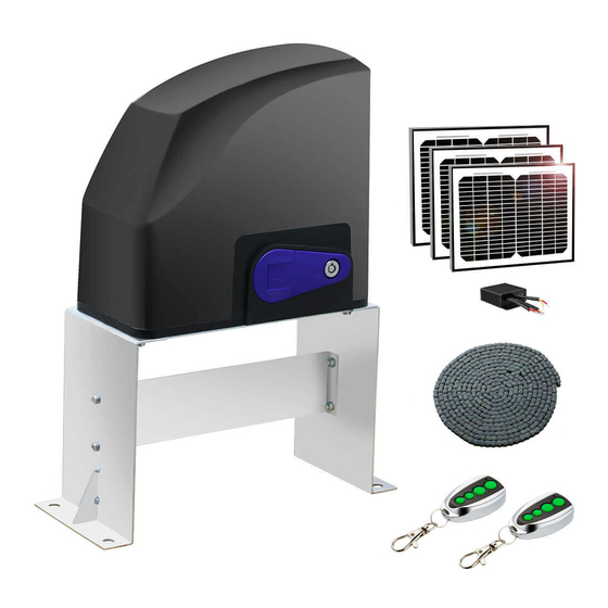
Sl i di ng Gate Opener
'
User
s Manual
Model :
DKC5 0 0 (S/Y )
TOPENS Website
www.topens.com
Email: support@topens.com
★ Please read and follow all warnings, precautions and instructions before
installation and use.
★ Never connect the solar panel to the control board directly to charge the battery.
★ Periodic checks of the opener are required to ensure safe operation.
★ Save this manual.
C030567
VER 21b
Advertisement
Table of Contents

Related Manuals for Topens DKC500


Summary of Contents for Topens DKC500
- Page 1 ’ User s Manual Model : DKC5 0 0 (S/Y ) TOPENS Website www.topens.com Email: support@topens.com ★ Please read and follow all warnings, precautions and instructions before installation and use. ★ Never connect the solar panel to the control board directly to charge the battery.
- Page 2 Visit: www.topens.com Please record the product model, your email address etc. in the spaces provided below. Refer to this list when contacting TOPENS for technical service or assistance with your automatic gate opener. Where did you purchase? (Amazon.com; Amazon.ca: Amazon.co.uk, Amazon.de; Other, Please...
-
Page 3: Table Of Contents
Parts List ................................4 Extra Parts ................................ 4 Accessories Parts (Included in some models, refers to the actual package) ..........5 Optional Accessories Parts List (Available at TOPENS Store) ................ 5 Replacement Parts ............................5 Technical Specifications & Features ........................ 6 Installation Overview ............................ -
Page 4: Check Your Gate Before Installation
Thank you for purchasing our sliding gate opener. We are sure that the products will be greatly satisfying as soon as you start to use it. The product is supplied with a user’s manual which encloses installation and safety precautions. These should be read carefully before installation and operation as they provide important information about safety, installation, operation and maintenance. -
Page 5: Preparation For Installation
• Position at least one visible indication device, and fix a Warning sign to the structure. • The factory declines all responsibility with respect to the automation safety and correct operation when other supplier’s components are used. • Only use original parts for any maintenance or repair operation. •... - Page 6 In sake of safety, a positive stop must be mounted on the two end of ground track.
-
Page 7: Parts List
Parts List Extra Parts... -
Page 8: Accessories Parts (Included In Some Models, Refers To The Actual Package)
TCS3 Solar Charge LT08B 20 Feet Roller Light Panel Charging Kit Controller Chain Replacement Parts DKPYMJ1B Control PYMJ-CKG Limit Switch Board WARNING: Changes or modifications not expressly specified by this user manual, TOPENS could void the warranty of this equipment. -
Page 9: Technical Specifications & Features
Technical Specifications & Features Specifications Model: DKC500(S/Y) Power input: 110~120V/60Hz or 220~240V/50Hz Motor voltage: 24VDC Rated power: 180W Gate moving speed: 21 cm/s (8.3 in/s) Max gate weight: 600kg (1300lbs) Environmental conditions: -20 ~ +50 ℃ ℃ -4°F to 122°F) -
Page 10: Installation Of The Opener
Installation of the Opener Caution: *Be sure that the opener is installed in a level and paralleled position. Improper installation could result in property damage, severe injury, and/or death. * Before starting installation, ensure that there is no point of friction during the entire movement of the gate and there is no danger of derailment. -
Page 11: Installation Of Chain And Chain Brackets
Installation of chain and chain brackets 1. Chain Brackets 1). Please refer to below chain brackets figure, which shows “U” bolt, “L” bracket and chain bolt. Use the “U” bolts (square or round) to attach the chain brackets to gate frame. 2). -
Page 12: Installation Of The Magnets
6). The chain brackets must be mounted to the same height as the chain on the idler wheels. 7). Make sure there is 1” distance at least between the wheel cover and the gate after you position the base plate. Installation of the Magnets Before install limit switch, make sure the gate opener is put in manual operation. -
Page 13: Connection Of The Power Supply
desired open position when the open limit switch approaches it. The magnet component with S pole must be installed at left side and the magnet component with N pole must be installed at right side from the view inside of property. Ensure magnet center to align with the marked line above ! The magnets should be 25~30mm (1-1.2”) away from the Limit Switch Box. - Page 14 Power Mode 3. Only use the batteries as the power source, only use the solar panel to charge the batteries If the AC electricity is not available, then you can choose the batteries as the power source and use the solar panel to charge the batteries.
-
Page 15: Connecting Of The Control Board
Connecting of the Control Board... - Page 16 1. Motor The YELLOW wire of the motor should be connected into the “1” terminal. The RED wire of the motor should be connected into the “2” terminal. 2. Limit Switches The YELLOW wire of the limit switches should be connected into the “3” terminal. The BLACK wire of the limit switches should be connected into the “4”...
-
Page 17: Setting Of The Control Board
7. Battery (ONLY included in Y Series) The “24V+” of the battery should be wired to the BAT+ (11) terminal, “24V-” should be wired to “-BAT” (10) terminal. If the battery has been used with solar panel, please connect the batteries and the solar panel &solar controller following the chapter of “Connection of the Power Supply”. - Page 18 DIP Switch #3–#5: Fine adjust the soft stop period of the motor DIP Switch #3: ON – 1 Second OFF – 0 DIP Switch #4: ON – 2 Seconds OFF – 0 DIP Switch #5: ON – 3 Seconds OFF – 0 NOTE: Every time you restart the gate opener after power off, you should use the access control device (such as remote, push button and etc.) to operate the gate opener to run for a complete opening cycle and a complete closing cycle to get the full opening time and the full closing time.
-
Page 19: Test The Reversing Sensitivity
250pcs remotes to be programmed for the opener. TOPENS ERM12 Universal External Receiver is available at TOPENS Store. † TOPENS ERM12 Universal External Receiver is also compatible with other brand swing gate opener, sliding gate opener and garage door opener. -
Page 20: How To Use The Remote To Operate Your Gate Opener
All of TOPENS sliding gate opener have midway mode. Button B is designed to realize midway function (refer to more details in our TOPENS sliding gate opener manual). So it is must program button A with sliding gate opener, while you may program either C button or D button with TOPENS swing gate opener. -
Page 21: Troubleshooting
Troubleshooting Have a multi-meter to check voltage and continuity. Use caution when checking high voltage terminals. Symptom Possible Solution(s) 1. Make sure that the power cord is properly plugged into the mains outlet. 2. Check if the output voltage of the transformer is 24VAC. If the voltage measures 0, the transformer may be overheated or damaged. -
Page 22: Maintenance
reverse 2. Check that the clutch is adjusted properly and is not slipping. 3. The opening force or closing force is adjusted too small. Turn the Potentiometer A&B to increase the force. 4. Disconnect the gate from the gate opener and check that the gate slides freely without any binding. - Page 23 Your comments and suggestions are important to us as they help us provide the best possible service. Should you have any need to contact us, the info below will help you get in touch: TOPENS Website www.topens.com Contact Us: E-mail: support@topens.com Kindly include your Product Model, Purchasing Date &...
Need help?
Do you have a question about the DKC500 and is the answer not in the manual?
Questions and answers