Table of Contents
Advertisement
★ Please read and follow all warnings, precautions and instructions before
installation and use.
★ Never connect the solar panel to the control board directly to charge the
battery.
★ Periodic checks of the opener are required to ensure safe operation.
★ Save this manual.
C030713
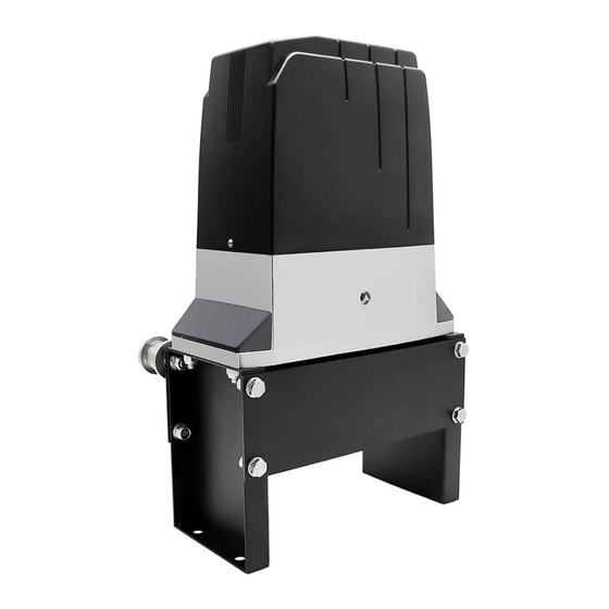
Sliding Gate Opener
User's Manual
Model:
DKC2000(S/Y)
TOPENS Website
www.topens.com
Email: support@topens.com
VER 23a
Advertisement
Table of Contents

Subscribe to Our Youtube Channel
Related Manuals for Topens DKC2000


Summary of Contents for Topens DKC2000
- Page 1 Sliding Gate Opener User’s Manual Model: DKC2000(S/Y) TOPENS Website www.topens.com Email: support@topens.com ★ Please read and follow all warnings, precautions and instructions before installation and use. ★ Never connect the solar panel to the control board directly to charge the battery.
- Page 2 Visit: www.topens.com Please record the product model, your email address etc. in the spaces provided below. Refer to this list when contacting TOPENS for technical service or assistance with your automatic gate opener. Where did you purchase? (Amazon.com; Amazon.ca: Amazon.co.uk, Amazon.de; Other, Please...
-
Page 3: Table Of Contents
Parts List ................................4 Extra Parts ................................ 4 Accessories Parts (Included in some models, refers to the actual package) ..........5 Optional Accessories Parts List (Available at TOPENS Store) ................ 5 Replacement Parts ............................6 Technical Specifications & Features ........................ 6 Features: ................................ -
Page 4: Check Your Gate Before Installation
Thank you for purchasing our sliding gate opener. We are sure that the products will be greatly satisfying as soon as you start to use it. The product is supplied with a user’s manual which encloses installation and safety precautions. These should be read carefully before installation and operation as they provide important information about safety, installation, operation and maintenance. -
Page 5: Preparation For Installation
danger caused by squashing, conveying and shearing. • Position at least one visible indication device, and fix a Warning sign to the structure. • The factory declines all responsibility with respect to the automation safety and correct operation when other supplier’s components are used. •... - Page 6 In sake of safety, a positive stop must be mounted on the two end of ground track.
-
Page 7: Parts List
Parts List Extra Parts... -
Page 8: Accessories Parts (Included In Some Models, Refers To The Actual Package)
Accessories Parts (Included in some models, refers to the actual package) Optional Accessories Parts List (Available at TOPENS Store) TC188 Universal ERM12 External M12 Remote Control Wireless and Wired TKP3 Wireless Keypad Receiver Keypad TEW3 Vehicle Sensor HLR01 HomeLink TC173 Wireless Push... -
Page 9: Replacement Parts
ZZDCPYMJ3A ZZJCKG Magnet Assembly(N pole Control Board Limit Switch & S pole) WARNING: Changes or modifications not expressly specified by this user manual, TOPENS could void the warranty of this equipment. Technical Specifications & Features Specifications Model: DKC2000(S/Y) Power input:... -
Page 10: Installation Overview
•Get the desired chain tension by adjusting the chain bolts Installation Overview Installation of the Opener Caution: *Be sure that the opener is installed in a level and paralleled position. Improper installation could result in property damage, severe injury, and/or death. * Before starting installation, ensure that there is no point of friction during the entire movement of the gate and there is no danger of derailment. -
Page 11: Manual Operation
heavy snow etc. 3. Prepare one or more conduits for the electrical cables before pour concrete. Remember that cable conduits have to pass through the hole on the base. 4. Pour concrete and before it starts to harden, check that it is parallel to the gate leaf and perfectly level. 5. - Page 12 5). Remove the unwanted length of chain. Set appropriated chain tension by adjusting two chain bolts of the both end. 6). The chain brackets must be mounted to the same height as the chain on the idler wheels. 7). Make sure there is 1” distance at least between the wheel cover and the gate after you position the base plate.
-
Page 13: Installation Of The Magnets
Installation of the Magnets Before install limit switch, make sure the gate opener is put in manual operation. (The clutch connected with gear shaft is disengaged) and the mains power supply is disconnected. Position Magnet Components approximately on the gate and move the gate by hand to fix them in place. - Page 14 Power Mode 1. Only use the AC electricity as the power source The power supply cord should be at least 2×0.75mm (2C×18AWG). Connect the live wire, neutral wire to the “L”, “N” terminals respectively. (PE is no need to be connected for this model of gate opener).
-
Page 15: Connection Between Master And Slave Gate Opener
Power Mode 4. By AC electricity and back-up batteries, use the AC electricity and the solar panel to charge the batteries at the same time If the AC electricity failure happens frequently and lasts for a long time (maybe lasts for 4-5 days one time), then you can charge the batteries with the AC electricity and the solar panel at the same time. -
Page 16: Connecting Of The Control Board
Connecting of the Control Board For SINGLE GATE OPENER, the connection of the control board can be simply referred to the following illustration. For DUAL GATE OPENER, you should configure the master gate opener and the slave gate opener firstly by setting the #2 dip switch of SW2 to ON. - Page 17 1. Motor The BLACK wire of the motor should be connected to the “MOTOR-” terminal (#25). The RED wire of the motor should be connected to the “+ MOTOR” terminal (#24). 2. Limit Switches The WHITE wire of the limit switches should be connected to the “HI” terminal (#10). The BLACK wire of the limit switches should be connected to the “COM”...
- Page 18 4. Warning Light (Included in some models, refers to the actual package) The BLACK wire of the warning light should be connected into the “Light DC24V-” terminal (#27). The RED wire of the warning light should be connected into the “Light DC+24V” terminal (#26). 5.
-
Page 19: Setting Of The Control Board
The BLACK wire of the wired keypad should be connected into the “COM” terminal (#8). The BLUE wire of the wired keypad should be connected into the “ONE” terminal (#4). The PURPLE wire of the wired keypad should be connected into the “COM” terminal (#1). 12. - Page 20 Auto-close time setting: 1. Turn and ONLY turn DIP Switch #3 and #6 to ON (All the other DIP switches of SW1 shall be turned OFF. They can be turned ON after the timer setting). 2. Press the button “ONE” to increase the timer from 1 second (Every time the timer will be start from 1 second when entering into the timer setting).
-
Page 21: How To Program Or Erase The Remote
SW2: DIP Switch #1: Type of the Limit Switch ON – Normally closed limit switch OFF –Normally open limit switch The limit switch which installed in the gate opener at the factory is normally open switch so this DIP switch shall be always set to OFF. -
Page 22: How To Use The Remote To Operate Your Gate Opener
All of TOPENS sliding gate opener have midway mode. Button B is designed to realize midway function (refer to more details in our TOPENS sliding gate opener manual). So it is must program button A with sliding gate opener, while you may program either C button or D button with TOPENS swing gate opener. -
Page 23: Troubleshooting
confirm the new setting in 15 seconds, the buzzer will beep for 8 short sounds continuously ((last for 2 seconds),, with LED flashing and then returning to on which indicates the keypad password has been changed successfully. You can press “PIN” “6 digits new password” and then press “OK” to confirm to operate the opener. - Page 24 2. Check the motor. Release the clutch then disconnect the wires of the motor from terminal 1 and 2. Connect the wires to 24V battery directly, the motor should run, and then exchange the wires, the motor should run in the opposite direction.
-
Page 25: Maintenance
Maintenance Every six months check the following items for proper operation of the unit. * Lubricate shafts and gears. * Keep opener clean at all times. * Check and tighten anchors bolts. * Check for loose or corroded wire * Ensure the opener is correctly terminated. * Always check the Stop/Reverse in case of obstruction function when performing any maintenance. - Page 26 Your comments and suggestions are important to us as they help us provide the best possible service. Should you have any need to contact us, the info below will help you get in touch: TOPENS Website www.topens.com Contact Us: E-mail: support@topens.com Kindly include your Product Model, Purchasing Date &...
Need help?
Do you have a question about the DKC2000 and is the answer not in the manual?
Questions and answers
Will a JD24VY 24V Warning Light work with my opener? If so how do I order one?
Yes, a JD24VY 24V Warning Light is compatible with the Topens DKC2000 opener. The manual specifies that the warning light should be powered by DC 24V, with the RED wire connected to the “Light DC+24V” terminal (#26) and the BLACK wire to the “Light DC24V-” terminal (#27), which matches the JD24VY specifications.
This answer is automatically generated