
Related Manuals for Lumag RP1400 PRO


Summary of Contents for Lumag RP1400 PRO
- Page 1 Distribution Limited Compactor Wacker Plate Operator’s Manual RP1400 PRO FOR YOUR SAFETY READ AND UNDERSTAND THE ENTIRE MANUAL BEFORE OPERATING THIS MACHINE...
- Page 3 For the warranty to be valid the Warranty Registration Form must be completed and returned to Lumag Distribution Limited within 14 days of the purchase, together with a copy of the purchase invoice. We will use your email to confirm that we have received the completed Warranty Registration Form and contact you about any errors or omissions on the form.
- Page 5 Lubricate X (2) Parts & Cables 1 – First service only, 2 = Should be carried out by your Lumag Dealer, 3 = May need to be done more often in dusty areas & 4 = Replace paper element only...
-
Page 7: Table Of Contents
CONTENT Ⅰ. INTRODUCTION............................- 2 - Ⅱ. APPLICATIONS ..........................- 2 - Ⅲ. STRUCTURE............................- 3 - Ⅳ. FUNCTIONS AND CONTROLS......................- 3 - Ⅴ. FOR SAFETY OPERATION........................- 3 - Ⅵ. HAZARDS AND RISKS ........................- 5 - Ⅶ. OPERATION............................- 7 - 7.1 PRIOR TO OPERATION.........................- 7 - 7.2 CAUTION............................ -
Page 8: Ⅰ. Introduction
Ⅰ. INTRODUCTION Thank you for your selection of our equipment. We have taken care in the design, manufacture and testing of this product. Should service or spare parts be required, prompt and efficient service is available from our branches. General Safety instructions for the Operation of Power Equipment. Our factory’s goal is to produce power equipment that helps the operator work safely and efficiently. -
Page 9: Ⅲ. Structure
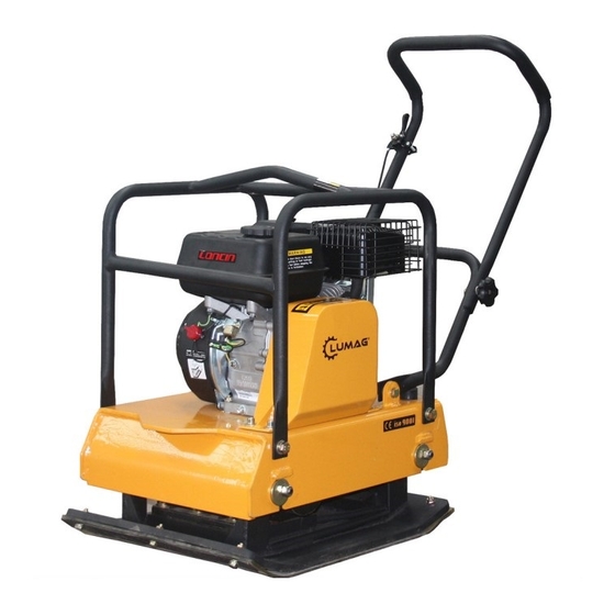
Ⅲ. STRUCTURE The upper part is made up of Power Source, Handle ,Belt Cover and Guard Hook which are fixed by Engine base. The Engine base is fixed on Vibrating Plate by Shock Absorbing Rubber.The lower part is made up of Vibrating Plate and Vibrator unit that has an Eccentric rotary shaft built in. The power source is transmitted from the centrifugal clutch on engine output shaft to the eccentric rotary shaft via V-belt. - Page 10 Safety: This section outlines basic safety procedures that apply to the operation,maintenance and adjustment of the plate compactor. This unit is designed as a powerful, productive machine that should be operated with respect and caution. Misuse or carelessness can result in serious injury or damage. or both. Safety precautions must be observed at all times.
-
Page 11: Ⅵ. Hazards And Risks
Ⅵ. HAZARDS AND RISKS NEVER allow any person to operate the machine without adequate instruction . ENSURE all operators read,understand and follow the operating instructions SERIOUS INJURY could result from improper or careless use of this machine Plate compactors are heavy units and should be positioned by two people of appropriate strength. Using the lifting handles provided on the machine, along with correct lifting techniques. - Page 12 DO NOT refuel the motor while it is in operation or hot. DO NOT refuel the motor in the vicinity of sparks, a naked flame or a person smoking. DO NOT over fill the fuel tank and avoid spilling petrol when refueling. Spilled petrol or petrol vapor may ignite.
-
Page 13: Ⅶ. Operation
Ⅶ. OPERATION GENERAL OPERATION The machine is best suited to the compaction of bituminous and granular materials e.g. granular soils, gravels and sands or mixtures of both. Cohesive soils such as silt and clay are best compacted using the impact force produced by a vibrating rammer. Where possible the site should be graded and leveled before commencing compaction. -
Page 14: Caution
If there is excess belt play. There could be a decrease in the impact force or erratic vibration, causing machine damage. 1-4. Check the engine oil level and if the engine oil lever is low, it should be refilled. Use the proper motor oil as suggested in the table below. -
Page 15: Starting
7.3 STARTING Gasoline Engine 3-1. Turn the STOP SWITCH clock-wise to the position “I”(ON) (Fig-3) 3-2.Open the fuel cock. (Fig-4) 3-3. Set the speed control lever 1/3 to 1/2 of the way towards the high speed position. (Fig-5) 3-4. Close the choke lever. If the engine is warm or the ambient temperature is high, open the choke lever half-way, or keep it fully open. -
Page 16: Operation
7.4 OPERATION 4-1. As the engine warms up, gradually move the choke lever to the OPEN position. (Fig-8) 4-2. Move the speed control lever from the LOW to the HIGH position. When the engine speed reaches approximately 2,300-2,600 PRM, the centrifugal clutch engages. -
Page 17: Shutdown
7.6 SHUTDOWN To stop the engine in an emergency, turn the stop switch to the OFF position. Under normal conditions, use the following procedure: 6-1. Set the speed control lever at the low speed position and allow the engine to run at low speed for 2 or 3 minutes before stopping.( Fig-11) 6-2.Tum stop... - Page 18 Keep the air cleaner element clean. URETHANE FOAM ELEMENT Remove the element and wash it in kerosene or diesel fuel. Then saturate it in a mixture of 3 parts kerosene or diesel fuel and 1 part engine oil. Squeeze the element to remove the mixture and install it in the air cleaner.
-
Page 19: Ⅷ. Care & Preventive Maintenance
Ⅷ. CARE & PREVENTIVE MAINTENANCE Check the oil level in the motor crankcase daily. Check the vibrator oil level weekly. Inspect the rubber anti vibration mounts for wear or deterioration. Clean the underside of the plate regularly to prevent a build up of material. -
Page 20: Ⅺ. Replacement Parts List
Ⅺ. REPLACEMENT PARTS LIST 10.1 MAJOR COMPONENTS - 14 -... - Page 21 PART NO. DESCRIPTION Vibrating plate Vibrator assembly Plate for engine mounting Engine Protective frame Flat key Circlip ø30 Bearing6206 Pulley Belt Centrifugal weight O spring Bigger washer¢8 Spring washer ¢8 Hexagonal bolt M8*30 Belt cover Socket head bolt M8*20 Spring washer ¢8 Flat washer ¢8 Socket head bolt M16*45 Spring washer ¢16...
-
Page 22: Vibrator Assembly
10.2 VIBRATOR ASSEMBLY - 16 -... - Page 23 PART NO. DESCRIPTION Paper cushion Case cover for pulley Oil seal 50*35*10 Flat washer ¢8 Spring washer ¢8 Hexagonal bolt M8*25 Pulley, driven Flat washer¢10 Spring washer ¢10 2-10 Air vent screw M10*30 2-11 Bearing 6309 2-12 Flat key 8*20 2-13 Ecc.
- Page 24 Unit 10, Hatchmoor Industrial Estate, Hatherleigh, Okehampton, Devon EX20 3LP www.lumag-gb.co.uk 01837 811741 Lumag Distribution Limited Company Number: 09267547 VAT Number: GB154566788 Hatherleigh Plant and Tool Hire is a trading name of Lumag Distribution LTD...
Need help?
Do you have a question about the RP1400 PRO and is the answer not in the manual?
Questions and answers