Table of Contents
Advertisement
Quick Links
Advertisement
Table of Contents

Related Manuals for Teltonika FM3200


Summary of Contents for Teltonika FM3200
- Page 1 FM3200 User Manual V1.3...
-
Page 2: Table Of Contents
Start Move Timeout – is a time interval required for movement sensor to be in the moving state, to consider vehicle as moving.....................................26 6.9.1 Monitoring ..............................27 6.9.2 Event Generating ............................27 6.9.3 Hysteresis ................................27 SMS COMMAND LIST ....................... 29 FM3200 ..........................29 SETTINGS FOR .............................29 COMMAND LIST getstatus ...................................30 getweektime ..................................31 getops ....................................31 getcfgtime ..................................31 getgps ....................................31 getver....................................31... - Page 3 setparam #### # ................................33 flush #,#,#,#,#,#,# ..............................33 DEBUG MODE........................... 34 PARAMETER LIST ........................35 ............................35 LOBAL ARAMETERS Record search (ID=105) ..............................35 Link timeout (ID=107) ..............................35 ...................35 ATA ACQUISITION AND SENDING PARAMETERS Time based acquire interval (ID=11) ..........................35 Distance based acquire interval (ID=12) ........................35 Angle based coordinate acquisition (ID=13) ........................35 Data Send interval (ID=270) ............................36 Minimum records number in packet (ID=232) .......................36...
-
Page 4: Introduction
FM3200 has USB interface; Please use cables provided with FM3200 device. Teltonika is not responsible for any harm caused by using wrong cables for PC <-> FM3200 connection. Attention! Internal battery must be plugged in, in order for FM3200 to work from backup battery. -
Page 5: Instructions Of Safety
• SMS – Short Message Service. • AC/DC – Alternating Current/Direct Current. • Record – AVL data stored in FM3200 memory. AVL data contains GPS and I/O information • AVL packet - Data packet that is being sent to server during data transmission. AVL packet... -
Page 6: Basic Description
BASIC DESCRIPTION FM3200 is a terminal with GPS and GSM connectivity, which is able to determine the object’s coordinates and transfer them via the GSM network. This device is perfectly suitable for applications, which need location acquirement of remote objects. It is important to mention that FM3200 has additional inputs and outputs, which let you control and monitor other devices on remote objects. -
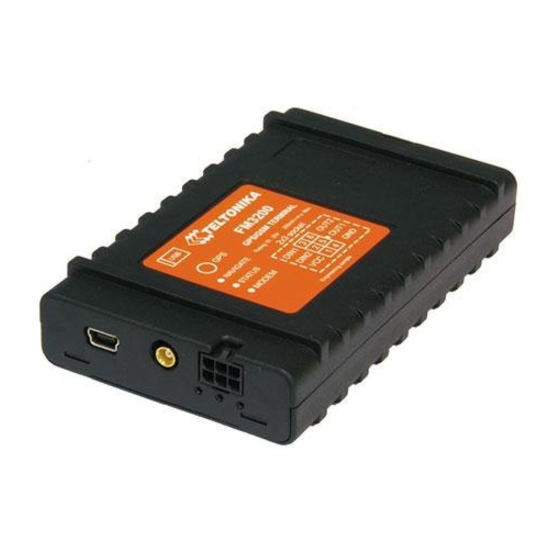
Page 7: Mechanical Features
GPS antenna connector MCX Operation temperature: GSM antenna connector SMA -25C ... +55C (optional) Storage temperature: Tyco Multi-Lock I/O MK-II C- -40C ... +70C Socket 2 175975 Storage relative humidity 5 ... 95 % (non condensation) Mini USB socket Figure 1. FM3200 specifications... -
Page 8: Technical Information
(SMS and GPRS), and accumulator age, number of charge/discharge cycles. For example: • In sleep mode a new FM3200 device’s operating time is approximately 3 h 30 min; • Operating time for a new FM3200 device, working in normal mode (records are being acquired every 10 sec and sent in packets of 4 records every 60 sec), is approximately 2 h. -
Page 9: Connection, Pinout, Accessories
CONNECTION, PINOUT, ACCESSORIES SIM card insert scheme ... -
Page 10: Installing Fm3200 Drivers
Screw the bolts. Installing FM3200 drivers In order to configure FM3200, “MS Windows XP Service Pack 2” or later version of MS Windows must be installed. “MS Windows XP SP2” Before connecting FM3200 to the computer, the special Hot Fixes must be installed: 1) Hotfix KB918365 (usbser.sys 5.1.2600.2930);... - Page 11 Figure 4. FM3200 installation step 2 The warning window will appear, click “Continue Anyway”. Figure 5. FM3200 installation step 3 Click “Finish”. The installation of “FM22XX Port” is completed. Immediately after the end of the installation, the new wizard for “FM22XX GPS” will appear. Repeat all the steps as in previous installation.
-
Page 12: Navigate Led
GPS is turned OFF (SLEEP mode) Modem LED When power is connected to FM3200, modem led is switched on permanently. Status LED When device has uploaded firmware – Status LED should blink. If LED does not blink – it means that device does not function. -
Page 13: Usb
FM3200 has USB interface; it has Mini USB connector type. FM3200 creates two COM-Ports: “FM32XX Port”, which can be used as system port (to flash firmware and configure the device) and “FM32XX GPS” as GPS NMEA 0183 output at 9600 baud rate. - Page 14 Alarm buttons, door sensors, etc. Alarm buttons, door sensors, ignition, etc. return two states: high or low voltage. Digital inputs are used to read this information. Figure below shows how to connect alarm button, door sensor, etc. Figure 10. Panic button connection In cases when sensor output signal is negative, an additional relay has to be installed to convert negative signal to positive.
- Page 15 Immobilizer relay When connected as shown below, FM3200 disables engine starter when output is OFF. More details about relays can be found below. Figure 12. Immobilizer relay connection Relays A simple automotive relay is used to invert input signal or to immobilize engine starter. Note, that they are available as 12 V or 24 V.
-
Page 16: Firmware
RILS stands for Remote Imlet Loading System, which is used to update FM3200 ARM processor firmware. In order to update firmware, server sends a SMS to the FM3200 and directs it to connect to the server and download new firmware. The special web interface is used for this operation. - Page 17 After logging in click on ‘Upload FM4’, click Browse near ‘Upload new firmware:’, select FM3200 firmware file from hard disk, click OK and then Upload. Select uploaded firmware from the list (last one) and click next. Enter necessary parameters in the fields: ...
-
Page 18: Operational Basics
It keeps adding these intervals until it is time to make a record, then FM3200 records its location and adds odometer value, which is equal to the sum of all distances, measured every second. When record is made, odometer resets to zero and distance calculation starts all over again. -
Page 19: Configuration
FM3200 Configurator program and selecting COM port. FM3200 has one user editable profile stored in Flash no. 1 memory and one extra profile stored in Flash no. 0, which cannot be edited by the user. Profile from Flash no. 0 is used by system and cannot be selected as active, while profile from Flash no. -
Page 20: System Settings
Angle based acquire value. If so, saves the record to memory. This check is being performed every second. FM3200 is able to collect records using three methods at the same time: time, distance and angle based data acquisition:... - Page 21 Time based data acquiring (Min. period) – records are being acquired every time when defined interval of time passes. Entering zero disables data acquisition depending on time. Distance based data acquiring (Min. distance) - records are being acquired when the distance between previous coordinate and current position is greater than defined parameter value.
-
Page 22: Geofence Settings
Geofence settings FM3200 has 5 configurable Geofence zones and it can generate event when defined Geofence zone border is crossed. • Frame border – frame border is an additional border around Geofence zone. It is additional area around defined zone used to prevent false event recording when object stops on the border of the area and because of GPS errors some records are made inside area and some –... -
Page 23: Gsm Settings
Records’ defines minimum number of coordinates and I/O data that should be transferred with one connection to server. If FM3200 does not have enough coordinates to send to server, it will check again after time interval defined in ‘Sending Period’ (see below). -
Page 24: Send Parameter Settings
At scheduled time match FM3200 checks for GPRS session activity. If GPRS session is alive, FM3200 sends data to server according to Send period parameter. If it is not, FM3200 checks if it is able to re-establish the session. -
Page 25: I/Osettings
• Operators list – FM3200 is able to use GPRS with all operators (operators list empty). If at least one operator is entered in the list, FM3200 is allowed to connect to GPRS only while operating in listed operator’s network. -
Page 26: Note: I/O Element's "Movement Sensor", Averaging Constant Is Interpreted As Start Move Timeout In Seconds (From 1 To 59)
SMS mode if SMS is enabled in SMS settings. • High and Low levels – define I/O value range. If I/O value enters or exits this range, FM3200 generates event. “Generate event” parameter defines when to generate event – when value enters defined range, exits it or both. -
Page 27: Monitoring
6.9.1 Monitoring I/O monitoring starts after enabling I/O element and setting up I/O parameters as it is shown below: 6.9.2 Event Generating Events happen when the value of enabled I/O intersects thresholds (enter, exit or on both) predefined by High and Low level thresholds. Table below defines all available values of I/O settings. Priority low, high High level... - Page 28 Figure 24. Event generation according hysteresis algorithm...
-
Page 29: Sms Command List
Essential fields in ‘SMS Settings’ are ‘Login’ and ‘Password’. This login and password should be used with every SMS sent to FM3200 as identifiers and means of protection from SMS from unauthorised numbers. Command structure: <login><space><password><space><command>... -
Page 30: Getstatus
deleterecords Delete all records saved on FLASH getio Readout digital inputs and outputs readio # Readout input value according entered ID, # - ID value setdigout ## set digital outputs 0 – OFF, 1 – ON DO1 DO2 DO3 DO4 getparam # Readout parameter value according entered # - ID value. -
Page 31: Getweektime
getweektime Response details Description Clock Sync Indicates system clock synchronization status. 0 – System is not synchronized, 1 – System synchronized Day Of Week – indicates current day of week starting from 0 – Monday, 1 – Tuesday, etc. Time Indicates current GMT time WeekTime Indicates time in minutes starting from Monday 00:00 GMT... -
Page 32: Getinfo
getinfo Response details Description Device Initialization Time RTC Time Restart Counter Error Counter Number of Sent Records Number of broken records Profile CRC Fail counter Failed GPRS counter Failed link counter UPD Timeout counter Sent SMS Counter NOGPS No GPS Timer GPS receiver state. -
Page 33: Setparam
setparam #### # Sets new value for parameter. ID consists of 4 digits – first digit identifies profile, second, third and fourth identifies parameter ID as described in Parameter List chapter. In value field a new parameter value is entered. Example: ‘setparam 1245 127.0.0.1’... -
Page 34: Debug Mode
Debug mode FM3200 is able to transmit its current state when connected to PC using USB cable. It is used to detect errors and provide information to possible solutions when operating as unexpected. Contact our sales manager to get terminal. -
Page 35: Parameter List
Parameter List FM3200 uses only one profile, therefore all changes to parameters must be done in profile1 (profile0 is for global parameters). Global Parameters Record search (ID=105) Record search parameter is responsible for record searching order. Value of 0 arranging data starting from newest, while value of 1 arranging data starting from oldest. -
Page 36: Data Send Interval (Id=270)
Minimum Maximum Recommended Goes with (depends on) parameters Value type value value value Time based acquire interval (ID=11) Distance based acquire interval (ID=12) Data Send interval (ID=270) Time interval in seconds, indicating frequency of sending data to server. 0 – disabled. Minimum Maximum Recommended... -
Page 37: Gprs Data Send Week Time Schedule (Id=272)
GPRS Data send week time schedule (ID=272) This parameter manages when it is allowed to open GPRS context. When module starts it is prohibited to open the context. When modem’s GPRS context is being closed (for example changing network) it is allowed to open it only at defined time. It is possible to allow connections every 10 minutes up to once per day. -
Page 38: Security Settings And Parameters
Minimum Maximum Recommended Goes with (depends on) parameters Value type value value value SMS Data send allow (ID=250)Format is described in the 4294967295 3600000 next chapter. SMS Data send week time schedule (ID=273) Security settings and parameters SMS User login (ID=252) User login is used to ensure module security. -
Page 39: Gprs Access And Address Settings
GPRS access and address settings APN Name (ID=242) Parameter defines GPRS Access Point Name. Minimum Maximum Recommended Goes with (depends on) parameters Value type value value value GPRS Enable (ID=240) 32 char Empty APN username (ID=243) S8[32] string APN Password (ID=244) APN username (ID=243) Parameter defines APN username. -
Page 40: Geofence Zones Settings And Parameters
Geofence zones settings and parameters This chapter explains how to get all parameters for the first GeoFence zone (all ID numbers are for the 1 zone). And at the end of the chapter (part 1.6.7) is presented a table with the IDs of all the rest GeoFence zones. -
Page 41: Geofence X2 (Id=033)
040 – 044 050 – 054 060 – 064 070 – 074 System parameters Sleep mode (ID=000) Parameter enables or disables sleep mode for FM3200: 0 – disabled, 1 – enabled. Minimum Maximum Recommended Goes with (depends on) parameters Value type... -
Page 42: Io Properties
Minimum Maximum Recommended Goes with (depends on) parameters Value type value value value Time based acquire interval (ID=11) Distance based acquire interval (ID=12) Angle based coordinate acquisition (ID=13) IO properties IO properties – are additional data sources which are recorded along with usual GPS data. IO#1 property parameter (ID=300) Parameter defines IO property value. -
Page 43: Io#1 Logic Operand (Id=304)
Minimum Maximum Recommended Goes with (depends on) parameters Value type value value value IO#1 property parameter (ID=300) IO#1 priority (ID=301) -2147483648 2147483648 IO#1 High level (ID=302) IO#1 logic operand (ID=304) IO#1 averaging length (ID=305) IO#1 logic operand (ID=304) Parameter defines when event is sent: 0: on range exit, 1: on range entrance, 2: both, 3: monitoring. -
Page 44: 10 Mounting Recommendations
• Avoid GPS antenna placement under metal surfaces. • Avoid placing FM3200 device near car radio, speakers or alarm systems (at least 30-40 cm). • Avoid placing GSM antenna near car radio, speakers or alarm systems (at least 30-40 cm). -
Page 45: 10.6 Module Installation
It is recommended to place GPS antenna behind dashboard as close to the window as possible. A good example of GPS antenna placement is displayed in a picture below (area colored green). Figure 28. Correct placement of FM3200 10.6 Module Installation •... -
Page 46: 11 Change Log
Comments 091103 Preliminary draft release. 091105 Added paragraph 6.9.3 Hysteresis, describing event generation according hysteresis algorithm. 091116 FM3200 view & dimensions figure added. 100211 New Skytraq GPS module details added. 100402 Movement sensor’s Start move timeout parameter’s description added. 100423 Data acquisition info updated.
Need help?
Do you have a question about the FM3200 and is the answer not in the manual?
Questions and answers