Teltonika FMB910 Quick Manual
Track & trace device
Hide thumbs
Also See for FMB910:
- Quick manual (20 pages) ,
- First start-up quick start manual (6 pages) ,
- How-to (5 pages)
Table of Contents
Advertisement
Quick Links
Advertisement
Table of Contents

Subscribe to Our Youtube Channel
Related Manuals for Teltonika FMB910


Summary of Contents for Teltonika FMB910
- Page 1 FMB910 Quick Manual v1.1 Track & trace device...
-
Page 2: Table Of Contents
Configuration (Windows) ..............7 Quick SMS configuration ..............9 Mounting recommendations ............10 LED indications ................. 11 Characteristics .................. 11 Basic characteristics ............... 11 Electrical characteristics ..............12 Safety information ................14 Certification and Approvals ............. 15 Wiki FMB910 |... -
Page 3: Know Your Device
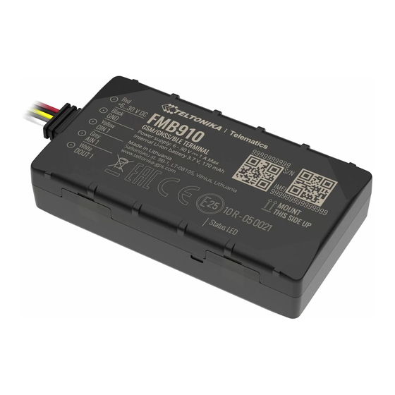
Know your device Figure 1 FMB910 device view Wiki FMB910 |... -
Page 4: Pinout
Pinout Table 1 FMB910 pinout PIN NUMBER PIN NAME DESCRIPTION (6-30) V DC (+) Power supply (6-30) V DC (+) GND (-) Ground pin Digital input, channel 1. DEDICATED DIN 1 FOR IGNITION INPUT Analog input, channel 1. Input range: 0-... -
Page 5: Wiring Scheme
Wiring scheme Figure 3 FMB910 Wiring scheme Automotive relay Wiki FMB910 |... -
Page 6: Set Up Your Device
Set up your device How to insert Micro SIM card and connect the battery 1. Gently remove FMB910 cover using plastic pry Figure 4 Cover removal Figure 5 Wiring harness connection tool from both sides. 2. Separate PCB from plastic cover and connect power supply cable. -
Page 7: Pc Connection (Windows)
PC Connection (Windows) 5. Setup will continue installing the driver and eventually the 1. Power-up FMB910 with DC voltage 6-30 V power supply using confirmation window will appear. Click Finish to complete the power cable. LED’s should start blinking, see “LED indications”. - Page 8 GNSS, GSM, I/O, Maintenance and etc. FMB910 has one user editable profile, which can be loaded and saved to the device. After any modification of configuration the changes need to be saved to device using Save to device button. Main buttons offer following...
-
Page 9: Quick Sms Configuration
2004 – Domain server every 120 2005 – Port • seconds After successful SMS configuration, FMB910 device will synchronize 2006 – Data sending protocol • (0 – TCP, 1 – UDP) time and update records to configured server. Time intervals and... -
Page 10: Mounting Recommendations
▬ When the module is connected, measure the voltage again to make sure it did not decrease. ▬ It is recommended to connect to the main power cable in the fuse box. ▬ 3 A, 125 V external fuse shall be used. Wiki FMB910 |... -
Page 11: Led Indications
Quad-band 850 / 900 / 1800 / 1900 2G bands GPRS Multi-Slot Class 12 (up to 240 Data transfer kbps), GPRS Mobile Station Class B Data support SMS (text/data) POWER Expected time in conditions with good GNSS satellites visibility Wiki FMB910 |... -
Page 12: Electrical Characteristics
Ignition detection Power Voltage, Engine RPM (OBDII PHYSICAL SPECIFICATION dongle) Dimensions 78.4 x 42.6 x 21 mm (L x W x H) Weight 69 g Electrical characteristics OPERATING ENVIRONMENT Operating temperature (without -40 °C to +85 °C battery) Wiki FMB910 |... - Page 13 DIGITAL INPUT = 2 mA) drain kΩ Input resistance (DIN1) Digital Input Voltage Input voltage (Recommended Operating Supply Analog Input Voltage Conditions) voltage Input Voltage threshold (DIN1) Analog Input error margin can increase if temperature varies. ANALOG INPUT Wiki FMB910 |...
-
Page 14: Safety Information
EN 60950-1 standard. instructions. • The device FMB910 is not designed as a navigational device for boats. Battery should not be disposed of with general Do not disassemble the device. If the device is household waste. Bring damaged or worn-out... -
Page 15: Certification And Approvals
This sign on the package means that all used electronic and electric equipment should not be mixed with general household waste. Hereby, Teltonika declare under our sole responsibility that the above described product is in conformity with the relevant Community harmonization: European Directive 2014/53/EU (RED). -
Page 16: Warranty
• Repaired • Replaced with a new product • Replaced with an equivalent repaired product fulfilling the same functionality • TELTONIKA can also repair products that are out of warranty at an agreed cost. Wiki FMB910 |...
Need help?
Do you have a question about the FMB910 and is the answer not in the manual?
Questions and answers