Advertisement
Quick Links
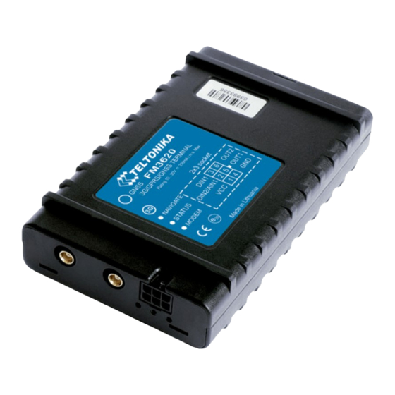
3G Tracking Device Installation Manual
Color
Red
Yellow
Yellow
Black
Purple
Purple
Most installations require only the first 3 wires. Red,
(Power, Ground and ignition). Other wires are typically used for additional
monitoring
requirements, such as temperature monitoring or Driver ID.
Any un-used wires should ideally be coiled up and kept for potential future
use, but can be cut if necessary (if cutting, it is our recommendation that at
least a 3 – 6cm lead be left so as to supply a fly lead for future connection
of additional monitoring devices).
3
2
1
Pin
Pin Name
1
10-30V DC (+)
2
Ignition
3
1-Wire Data
4
Ground (-)
5
Digital Output 1
6
1-Wire Power
6
5
4
Description
Power supply for module.
Digital input 1
Data channel for Dallas devices
Ground pin
Digital output. Open collector
output. Max. 150mA.
+ 3,8 V output for 1-Wire®
Black
and
Yellow
Advertisement

Related Manuals for Teltonika fm3620


Summary of Contents for Teltonika fm3620
- Page 1 3G Tracking Device Installation Manual Color Pin Name Description 10-30V DC (+) Power supply for module. Yellow Ignition Digital input 1 Data channel for Dallas devices Yellow 1-Wire Data Black Ground (-) Ground pin Purple Digital Output 1 Digital output. Open collector output.
- Page 2 Installation best practices • Wires should be connected while GPS device is not plugged in. • Wires should be fastened to the other wires (excluding air bag wires) or non-moving parts. Avoid heat emitting and moving objects near the wires, modules or antennas. •...
- Page 3 Placing antennas • Avoid placing antennas under metal surfaces. • Avoid easily reachable places. • Antennas should be placed as horizontal as possible (GPS antennas in- stalled on an angle greater than 30 degrees are considered incorrectly mounted and may cause faulty signal reading). •...
Need help?
Do you have a question about the fm3620 and is the answer not in the manual?
Questions and answers