Table of Contents
Advertisement
Quick Links
Instructions-Parts
Python
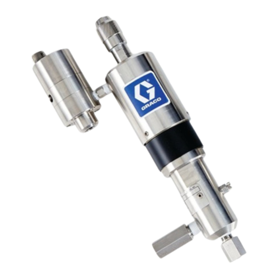
Injection Pump
Pneumatic pump for injecting chemicals at well sites. Not for use with sour gas. For
professional use only.
Not approved for use in European explosive atmosphere locations.
See page 3 for model information, including maximum working
pressures.
Important Safety Instructions
Read all warnings and instructions in this manual.
Save all instructions.
™
Chemical
3A3101F
EN
Advertisement
Table of Contents

Related Manuals for Graco Python A25030


Summary of Contents for Graco Python A25030
- Page 1 Instructions-Parts ™ Python Chemical Injection Pump 3A3101F Pneumatic pump for injecting chemicals at well sites. Not for use with sour gas. For professional use only. Not approved for use in European explosive atmosphere locations. See page 3 for model information, including maximum working pressures.
-
Page 2: Table Of Contents
Technical Data ......55 Graco Standard Warranty ....56... -
Page 3: Models
Models Models Maximum Working Pressure Maximum Pneumatic Inlet Pressure Plunger Size Air Motor Size psi (MPa, bar) psi (MPa, bar) 1/8 in. 12,000 (82.7, 827) 170 (1.17, 11.7) 3/16 in. 6500 (44.8, 448) 1/4 in. 3500 (24.1, 241) 3/8 in. 1-1/4 in. -
Page 4: Configuration Number Matrix
Configuration Number Matrix Configuration Number Matrix Check the identification plate (ID) for the 12-digit Configuration Number of your pump. Use the following matrix to define the components of your pump. NOTE: Not all combinations are possible. Sample Configuration Number: PCI-125-19S-XA-0 Pneumatic Air Motor Size Plunger Size Pressure Range Plunger Material... -
Page 5: Warnings
Warnings Warnings The following warnings are for the setup, use, grounding, maintenance, and repair of this equipment. The exclama- tion point symbol alerts you to a general warning and the hazard symbols refer to procedure-specific risks. When these symbols appear in the body of this manual or on warning labels, refer back to these Warnings. Product-specific hazard symbols and warnings not covered in this section may appear throughout the body of this manual where applicable. - Page 6 Warnings PERSONAL PROTECTIVE EQUIPMENT Wear appropriate protective equipment when in the work area to help prevent serious injury, including eye injury, hearing loss, inhalation of toxic fumes, and burns. Protective equipment includes but is not limited to: • Protective eyewear, and hearing protection. •...
-
Page 7: Component Identification
Component Identification Component Identification . 1 Pump Components Numbered items in the key below correspond to the numbers in the Parts Lists starting on page 36. Key: Air Motor Housing Air Piston Cylinder Dust Shield Fluid Cylinder Inlet Valve Check Outlet Valve Check Priming Bleed Valve Pump Stroke Adjuster... -
Page 8: Installation
Installation Installation Required Accessories Install the following required accessories in the order shown in F . 2, using adapters as necessary. See Kits Grounding and Accessories starting on page 42. Air Line • Bleed-type master air valve (D): required in your The equipment must be grounded to reduce the risk system to relieve air trapped between it and the air of static sparking. -
Page 9: Typical Installation
Chemical Supply from what is shown here. (See Required Accessories, page 8.) The Python pump (F) is the only component in . 2 supplied by Graco. All other components are sup- plied by customer. Key: If you have an application, or mounting configuration,... -
Page 10: Connect Pneumatic Supply
Installation Connect Pneumatic Supply NOTE: A pressure relief valve is available from Graco and can be connected back to the tank or directly to the inlet side of the pump. See Kits and Accessories on 1. Install the pneumatic regulator (E) and gauge to page 42. - Page 11 Installation Minimum Gas Pressures by Fluid Plunger Size and Outlet Pressures See Performance Charts, starting on page 44, for maximum flows at any given pressure. 1/8 in. Fluid Plunger Pumps 3/16 in. Fluid Plunger Pumps Minimum Gas Pressure Minimum Gas Pressure psi (MPa, bar) psi (MPa, bar) Outlet Pressure...
- Page 12 Installation 1/4 in. Fluid Plunger Pumps Minimum Gas Pressure psi (MPa, bar) Outlet Pressure psi (MPa, bar) 1.25 in. Air Motor1.75 in. Air Motor 2 in. Air Motor 0 (0, 0) 50 (0.34, 3.4) 50 (0.34, 3.4) 50 (0.34, 3.4) 250 (1.7, 17.2) 60 (0.41, 4.1) 50 (0.34, 3.4)
- Page 13 Installation 3/8 in. Fluid Plunger Pumps Minimum Gas Pressure psi (MPa, bar) Outlet Pressure psi (MPa, bar) 1.25 in. Air Motor 1.75 in. Air Motor 2 in. Air Motor 0 (0, 0) 50 (0.34, 3.4) 50 (0.34, 3.4) 50 (0.34, 3.4) 150 (1, 10.3) 63 (0.44, 4.4) 50 (0.34, 3.4)
- Page 14 Installation 1/2 in. Fluid Plunger Pumps Minimum Gas Pressure psi (MPa, bar) Outlet Pressure psi (MPa, bar) 1.25 in. Air Motor 1.75 in. Air Motor 2 in. Air Motor 0 (0, 0) 50 (0.34, 3.4) 50 (0.34, 3.4) 50 (0.34, 3.4) 100 (0.7, 6.9) 66 (0.45, 4.5) 50 (0.34, 3.4)
- Page 15 Installation 5/8 in. Fluid Plunger Pumps Minimum Gas Pressure psi (MPa, bar) Outlet Pressure psi (MPa, bar) 1.25 in. Air Motor 1.75 in. Air Motor 2 in. Air Motor 0 (0, 0) 50 (0.34, 3.4) 50 (0.34, 3.4) 50 (0.34, 3.4) 75 (0.5, 5.2) 68 (0.47, 4.7) 50 (0.34, 3.4)
- Page 16 Installation 3/4 in. Fluid Plunger Pumps Minimum Gas Pressure psi (MPa, bar) Outlet Pressure psi (MPa, bar) 1.25 in. Air Motor 1.75 in. Air Motor 2 in. Air Motor 0 (0, 0) 50 (0.34, 3.4) 50 (0.34, 3.4) 50 (0.34, 3.4) 50 (0.3, 3.4) 68 (0.47, 4.7) 50 (0.34, 3.4)
-
Page 17: Operation
Operation Operation Pressure Relief Procedure sure. (Use a hex wrench for PCI-xxx-xxH pumps. See Configuration Number Matrix, page 4.) Follow the Pressure Relief Procedure whenever 5. Slowly disconnect fluid lines (K & P) from check you see this symbol. valves (L & M). 6. -
Page 18: Prime The Pump
Operation Prime the Pump 1. Verify all connections and fluid lines are tight. 2. In order to prime the pump, turn the prime valve (20) counter-clockwise. NOTE: PCI-xxx-xxH pumps feature a one-piece valve (19) that requires a hex wrench to turn. See Configura- tion Number Matrix, page 4. -
Page 19: Calibrate Chemical Dosage
Operation Calibrate Chemical Dosage Stroke Adjustment This pump has infinite stroke adjustment between full and 1/4 stroke, and has four marked stroke adjustment positions. 1. Begin the process by setting the timing valve (22) to an estimated setting of the flow rate. See Baseline Chemical Dosage Settings, page 20, for tables of cycles per minute (CPM), and corresponding gal- lons per day (GPD) and liters per day (LPD). - Page 20 Operation Baseline Chemical Dosage Settings See Stroke Adjustment, page 19, for stroke adjust settings. See Performance Charts, starting on page 44, for maximum flows at any given pressure. 1/8 in. Fluid Plunger Pumps 3/16 in. Fluid Plunger Pumps GPD (LPD) GPD (LPD) Full Stroke 3/4 Stroke...
- Page 21 Operation 1/2 in. Fluid Plunger Pumps 5/8 in. Fluid Plunger Pumps GPD (LPD) GPD (LPD) Full Stroke 3/4 Stroke 1/2 Stroke 1/4 Stroke Full Stroke 3/4 Stroke 1/2 Stroke 1/4 Stroke 4.9 (18.5) 3.7 (13.9) 2.4 (9.3) 1.2 (4.6) 7.6 (29.0) 5.7 (21.7) 3.8 (14.5) 1.9 (7.2)
-
Page 22: Maintenance
Maintenance Maintenance Preventive Maintenance Schedule The operating conditions of your particular pump deter- mines how often maintenance is required. Establish a preventive maintenance schedule by recording when and what kind of maintenance is needed, and then determine a regular schedule for checking your pump. Tighten Threaded Connections Check that all threaded connections are tight at routine intervals. -
Page 23: Troubleshooting
Troubleshooting Troubleshooting 1. Follow Pressure Relief Procedure, page 17, before checking or repairing pump. 2. Check all possible problems and causes before dis- assembling pump. Problem Cause Solution Air bubbles in fluid Suction line is loose Tighten Timing valve not cycling Debris in timing valve Clean or rebuild timing valve Worn timing valve seals... -
Page 24: Repair
Repair Repair Before servicing or repairing your pump, verify that pressure is relieved according to the Pressure Relief Procedure, page 17, and that all fluid and pneumatic lines are properly shut off, or sealed with compatible valves and disconnected. Pump 4. - Page 25 Repair Pump Repair 3. Replace packing (15) and bearings (14), if neces- sary. Lubricate prior to reassembly. 1. Remove packing nut (16) from fluid cylinder (13). 2. Carefully remove bearings (14) and packing (15) from the fluid cylinder (13). Gray Seal lips Gray facing down...
- Page 26 Repair Reconnect Fluid Cylinder 3. Tighten the packing nut (16) to a torque of 15 in-lbs (1.7 N•m), then loosen and tighten again it to a final 1. Carefully guide the fluid plunger (5) into the packing torque of 5 in-lbs (0.6 N•m). nut (16) and through the packing (15) as the threads on the fluid cylinder (13) are brought closer to the air motor housing (1).
- Page 27 Repair Remove Air Piston and Fluid Plunger NOTE: The upper air motor is under light spring tension; therefore, it is necessary to hold downward pressure on Assembly the air piston cylinder (8) as the set screws (10) are 1. Follow the Pressure Relief Procedure, page 17. loosened.
- Page 28 Repair Replace Air Motor Seal Air Piston, Fluid Plunger, and Upper Cylinder Reassembly NOTE: PCI-xxx-xxx-xx-U configurations (see Configu- ration Number Matrix on page 4) use a U-cup seal that NOTE: PCI-xxx-xxx-xx-U configurations (see Configu- replaces the air piston o-ring (7). ration Number Matrix on page 4) use a U-cup seal that replaces the air piston o-ring (7).
-
Page 29: Check Valves
Repair air piston cylinder is brought closer to the air motor Check Valves housing. Light pressure is required to keep the air piston cylinder in place. Ensure the cylinder (8) is pushed down to the hard stop so that the set screws (10) engage the groove. - Page 30 Repair Inlet Check Valve Repair (models Outlet Check Valve Repair (all models PCI-xxx-xxH only) except PCI-xxx-xxH) 1. Follow the Pressure Relief Procedure, page 17. 1. Follow the Pressure Relief Procedure, page 17. 2. Remove the inlet check valve assembly (17). 2.
- Page 31 Repair Outlet Check Valve Repair (models PCI-xxx-xxH only) 1. Follow the Pressure Relief Procedure, page 17. 2. Remove the outlet check valve assembly (18). . 20 Outlet check valve assembly 3. Separate the front housing (18e) from the back housing (18f). 4.
-
Page 32: Timing Valve
Repair Timing Valve 5. Pull the spool (103) out of the lower housing (101). Inspect and replace as necessary. Timing Valve Repair 1. Follow the Pressure Relief Procedure, page 17. 2. Remove the spring retainer (112) from the bottom of the timing valve. - Page 33 (118) and replace as necessary. 9. Inspect the seal (108) and piston (107), and replace if necessary. The repair parts from Graco come as a 13. Clean and inspect all parts before reassembly. piston assembly with the seals factory installed.
- Page 34 Repair 16. Place the timing valve knob (122) over the needle the housing lead-in (130) to ease installation and valve (117), with the “0” lined up with the marker on ensure that the seals are not damaged. the label (121). Tighten the hex set screws (123). Marker Lead-in 102 (w/105 &...
- Page 35 Repair 20. Connect the upper and lower housings by lining up Final Reassembly the dowel pins (113) in lower housing (101) with the 1. After all inspections and repairs are completed, receiving holes in the upper housing (110). Tighten reconnect all fluid lines. the screws (111).
-
Page 36: Parts
Parts Parts Python Pneumatic Pump PCI-200-13S-SA-0 shown 3A3101F... - Page 37 Parts Python Pneumatic Pump Parts List Ref. Part Description Qty. B32176 O-ring packing, for 1/2” and smaller Ref. Part Description Qty. fluid plungers; included with dust B32163 Air motor housing, for 1/2” and shield (ref. 12) smaller fluid plungers B32177 O-ring packing, for 5/8”...
- Page 38 Parts Table 1: Fluid Plunger Springs (ref. 4), including Plunger Wipers (ref. 3) Part Numbers by Fluid Plunger Size Diameter 1/8 in. 3/16 in. 1/4 in. 3/8 in. 1/2 in. 5/8 in. 3/4 in. Qty. B32167 B32167 B32167 B32168 B32169 B32170 B32171 Table 2: Fluid Plungers (ref.
- Page 39 Parts Table 5: Packing Nuts (ref. 16) Part Numbers by Fluid Plunger Size Diameter 1/8 in. 3/16 in. 1/4 in. 3/8 in. 1/2 in. 5/8 in. 3/4 in. Qty. B32187 B32187 B32187 B32188 B32203 B32190 B32190 Table 6: Inlet Valve Check (ref. 17) Part Numbers by Fluid Plunger Size Diameter 1/8 in.
-
Page 40: Python Timing Valve Assembly
Parts Python Timing Valve Assembly B32069 123‡ 108* 107* 106* 104* 103* 125* 105* 124* 102* ‡ 105* 124* 130* 105* 124* 102* 105* 124* 129* 3A3101F... - Page 41 Parts Timing Valve Assembly (B32069) Parts List Ref. Part Description Qty. Ref. Part Description Qty. Internal Ring, Stainless Steel; B32193 Lower Housing included with timing valve nee- 102* Seal Cartridge dle (ref. 117) 103* Spool Knob Spring; included with tim- 104* Ball, 316 stainless steel;...
-
Page 42: Kits And Accessories
Kits and Accessories Kits and Accessories Additional Kits & Accessories B32235 FFKM Small (1/8” - 1/4”) Inlet and Outlet Check Valve Repair Kit (includes a spring Part No. Description and piston o-rings) B32045 225-750 PSI Pressure Relief Valve Kit B32234 HNBR Small (1/8”... -
Page 43: Dimensions
Dimensions Dimensions Python Pump Dimensions . 30 Python Pump Dimensions Pump Size 125-13H 13.35 in. (33.9 cm) 4.30 in. (10.9 cm) 2.15 in. (5.5 cm) 2.45 in. (6.2 cm) 9.54 in. (24.2 cm) 175-13H 13.10 in. (33.3 cm) 4.68 in. (11.9 cm) 2.15 in. -
Page 44: Performance Charts
Performance Charts Performance Charts 1 1/4” Air Motors (PCI-125) 1/8” Plunger (PCI-125-13) (17.0) (15.1) (13.3) Inlet Pressure - (11.4) (LPD) (MPa, Bar) (9.5) A-50 (0.35, 3.5) B-100 (0.69, (7.6) 6.9) (5.7) (3.8) (1.9) 2000 4000 6000 8000 10000 12000 (13.79) (27.58) (41.37) (55.16) - Page 45 Performance Charts 3/16” Plunger (PCI-125-19) (45.4) (37.9) Inlet Pressure (30.3) - PSI (LPD) (MPa, Bar) A-50 (0.35, (22.7) 3.5) B-100 (0.69, (15.2) (7.6) 1000 2000 3000 4000 5000 6000 7000 (6.89) (13.79) (20.68) (27.58) (34.47) (41.37) (48.26) (68.9) (137.9) (206.8) (275.8) (344.7) (413.7)
- Page 46 Performance Charts 3/8” Plunger (PCI-125-38) (170) (151) (133) Inlet Pressure (114) - PSI (LPD) (MPa, Bar) (95) A-50 (0.35, 3.5) (76) B-100 (0.69, (57) (38) (19) 1000 1200 1400 1600 1800 (1.38) (2.76) (4.14) (5.52) (6.90) (8.27) (9.65) (11.03) (12.41) (13.8) (27.6) (41.4)
- Page 47 Performance Charts 5/8” Plunger (PCI-125-63) (454) (379) Inlet Pressure (303) - PSI (LPD) (MPa, Bar) A-50 (0.35, (227) 3.5) B-100 (0.69, (151) (76) (0.69) (1.38) (2.07) (2.76) (3.45) (4.14) (6.9) (13.8) (20.7) (27.6) (34.5) (41.4) Outlet Pressure - PSI (MPa, Bar) .
-
Page 48: 3/4" Air Motors (Pci-175)
Performance Charts 1 3/4” Air Motors (PCI-175) 1/8” Plunger (PCI-175-13) (15.1) (13.3) (11.4) Inlet Pressure (9.5) - PSI (LPD) (MPa, Bar) A-50 (0.35, (7.6) 3.5) B-100 (0.69, (5.7) (3.8) (1.9) 2000 4000 6000 8000 10000 12000 14000 (13.79) (27.58) (41.37) (55.16) (68.95) (82.74) - Page 49 Performance Charts 1/4” Plunger (PCI-175-25) (68.1) (60.6) (53.0) Inlet Pressure (45.4) - PSI (MPa, Bar) (LPD) (37.9) A-50 (0.35, 3.5) (30.3) B-100 (0.69, (22.7) (15.2) (7.6) 1000 2000 3000 4000 5000 6000 7000 8000 (6.89) (13.79) (20.68) (27.58) (34.47) (41.37) (48.26) (55.16) (68.9)
- Page 50 Performance Charts 1/2” Plunger (PCI-175-50) (303) (265) (227) Inlet Pressure - PSI (189) (LPD) (MPa, Bar) A-50 (0.35, (151) 3.5) B-100 (0.69, (114) (76) (38) 1000 1500 2000 (3.45) (6.90) (10.34) (13.79) (34.5) (69.0) (103.4) (137.9) Outlet Pressure - PSI (MPa, Bar) .
-
Page 51: 2" Air Motors (Pci-200)
Performance Charts 3/4” Plunger (PCI-175-75) (681) (606) (530) Inlet Pressure - (454) (MPa, Bar) (LPD) (379) A-50 (0.35, 3.5) B-100 (0.69, (303) 6.9) (227) (151) (76) (0.69) (1.38) (2.07) (2.76) (3.45) (4.14) (6.9) (13.8) (20.7) (27.6) (34.5) (41.4) Outlet Pressure - PSI (MPa, Bar) . - Page 52 Performance Charts 3/16” Plunger (PCI-200-19) (30.3) (26.5) Inlet Pressure (22.7) - PSI (MPa, Bar) (19.0) A-50 (0.35, (LPD) 3.5) (15.2) B-100 (0.69, (11.4) (7.6) (3.8) 2000 4000 6000 8000 10000 12000 14000 (13.79) (27.58) (41.37) (55.16) (68.95) (82.74) (96.53) (137.9) (275.8) (413.7) (551.6)
- Page 53 Performance Charts 3/8” Plunger (PCI-200-38) (170) (151) (133) Inlet Pressure - (114) (MPa, Bar) (LPD) (95) A-50 (0.35, 3.5) (76) B-100 (0.69, (57) (38) (19) 1500 2500 3500 1000 2000 3000 4000 4500 (3.45) (6.89) (10.34) (13.79) (17.24) (20.68) (24.13) (27.58) (31.03) (34.5)
- Page 54 Performance Charts 5/8” Plunger (PCI-200-63) (454) (379) Inlet Pressure (303) - PSI (LPD) (MPa, Bar) A-50 (0.35, (227) 3.5) B-100 (0.69, (151) (76) 1000 1200 1400 (1.38) (2.76) (4.14) (5.52) (6.90) (8.27) (9.65) (13.8) (27.6) (41.4) (55.2) (69.0) (82.7) (96.5) Outlet Pressure - PSI (MPa, Bar) .
-
Page 55: Technical Data
Technical Data Technical Data Python Chemical Injection Pump Metric Maximum air inlet pressure See Models on page 3. Maximum fluid working pressure See Models on page 3. Environmental temperature range -40°–176°F -40°–80°C Noise (dBa) Maximum sound pressure <70 dBa with included muffler installed. Inlet/Outlet Sizes Fluid inlet size 1/4 in. -
Page 56: Graco Standard Warranty
With the exception of any special, extended, or limited warranty published by Graco, Graco will, for a period of twelve months from the date of sale, repair or replace any part of the equipment determined by Graco to be defective.
Need help?
Do you have a question about the Python A25030 and is the answer not in the manual?
Questions and answers