Table of Contents
Advertisement
Instructions
Modu-Flo
For dispensing a specific volume of lubricant. For use with Graco Modu-Flo manifold
packages. For professional use only.
Part No.:
Pneumatic - 563304, 563306, 563308, 563347, 563348, 563351, 563353, 563354
Hydraulic - 563305, 563307, 563345
See page 2 for model information, including maximum working pressure.
Important Safety Instructions
Read all warnings and instructions in this
manual before using the equipment. Save all
instructions.
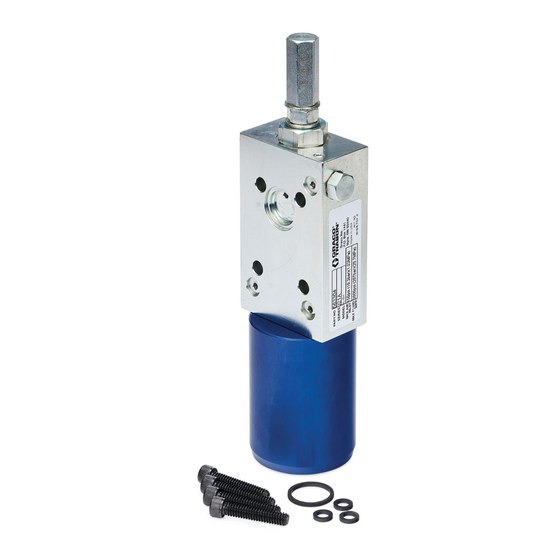
Hydraulic Pump
®
Pumps
ti20044
Pneumatic Pump
332042D
EN
ti20035
Advertisement
Table of Contents

Related Manuals for Graco Modu-Flo AL-5M


Summary of Contents for Graco Modu-Flo AL-5M
- Page 1 Instructions ® Modu-Flo Pumps 332042D For dispensing a specific volume of lubricant. For use with Graco Modu-Flo manifold packages. For professional use only. Part No.: Pneumatic - 563304, 563306, 563308, 563347, 563348, 563351, 563353, 563354 Hydraulic - 563305, 563307, 563345 See page 2 for model information, including maximum working pressure.
-
Page 2: General Information
Models Models Input Air/ Input Max. Hydraulic Air or Output Max. Operating Approx. Fluid Pressure Pump Hydraulic Displacement Cycles Volume Part No. Model Actuation Weight, Output PSI (bar) Ratio Motor Range cu.in. (cm³) per Full lb (kg) Pressure Action* per stroke Minute** stroke/cycle PSI (bar) - Page 3 Warnings Warnings The following warnings are for the setup, use, grounding, maintenance, and repair of this equipment. The exclamation point symbol alerts you to a general warning and the hazard symbols refer to procedure-specific risks. When these symbols appear in the body of this manual or on warning labels, refer back to these Warnings. Product-specific hazard symbols and warnings not covered in this section may appear throughout the body of this manual where applicable.
- Page 4 Warnings WARNING EQUIPMENT MISUSE HAZARD Misuse can cause death or serious injury. • Do not operate the unit when fatigued or under the influence of drugs or alcohol. • Do not exceed the maximum working pressure or temperature rating of the lowest rated system component.
-
Page 5: Installation
Installation Installation Component Identification ti20035 Key: Single Acting (S.A.) Port Double Acting (D.A.) Port Mounting Holes Lube Inlet Port Lube Outlet Port Adjustment Cover Bleed Screw 332042D... -
Page 6: Pressure Relief Procedure
Installation Installation Pressure Relief Procedure 1. Follow the Pressure Relief Procedure, page 6. 2. Remove adjustment screw cap (12) and gasket (8) Follow the Pressure Relief Procedure whenever from adjustment screw (11), holding jam nut (9) with you see this symbol. a wrench if necessary (F . -
Page 7: Troubleshooting
Troubleshooting Troubleshooting 1. Follow Pressure Relief Procedure, page 6, before Reference numbers used in the following procedure checking or repairing gun. refer to the Parts table, pages 8, 10, or 11. Problem Cause Solution 1. Check four socket head screws Inconsistent Pump Output Air and/or lubricant leak between (7) to make sure they are tight. -
Page 8: Pneumatic Pump
Parts Parts Pneumatic Pump Part No./Description Ref. Part Description Qty. Ref. Part Description Qty. 557589 SCREW, adjustment, AL-5M 563304 PUMP ASSEMBLY, AL-5M 15R126 SCREW, adjustment, AL-25M 563306 PUMP ASSEMBLY, AL-25M 560740 SCREW, adjustment, AL-50M 563308 PUMP ASSEMBLY, AL-50M 560737 CAP, adjustment screw, AL-5M 1❄... - Page 9 Parts Ref. Part Description Qty. 560708 CYLINDER, air, AL-5M 557565 CYLINDER, air, AL-25M 560723 CYLINDER, air, AL-50M 20❄ LABEL, name serial ✿★◆ O-RING ✿★◆ O-RING ✿★◆ O-RING ✿★◆ O-RING ✿★◆ O-RING ✿★◆ O-RING ✿★◆ O-RING ✿★◆ BALL, sst 1/8” dia ✿★◆...
- Page 10 Parts Hydraulic Pump (HLJ-5M and HLJ-5X) 18 17 HL-5 model HL-5X model ti20046 Part No./Description Ref. Part Description Qty. Ref. Part Description Qty. O-RING 563305 PUMP ASSEMBLY, HLJ-5M ❖ O-RING 563345 PUMP ASSEMBLY, HLJ-5X ❖✿ 1❄ LABEL, name serial O-RING ❖✿...
- Page 11 Parts Hydraulic Pump (HLJ-25M) ti20048 Part No./Description Part Description Qty. Part Description Qty. O-RING 563307 PUMP ASSEMBLY, HLJ-25M ❖ O-RING ❖ ❖ O-RING SPRING, check valve ❖ ❖ O-RING 3❄ BODY, pump ❖ O-RING 557568 CYLINDER, hydraulic ❖ RING, backup 560716 PLUG, end ❖...
- Page 12 Notes Notes 332042D...
-
Page 13: Technical Specifications
Technical Specifications Technical Specifications Modu-Flo Metric Pressure 40 - 150 psi 0.276 MPa (2.76 bar) - 1 MPa Air Pressure (10.3 bar) 200 - 2000 psi 1.38 MPa (13.8 bar) - 13.8 Hydraulic Pressure MPa (138 bar) Lube to Air Pressure Ratio 30:1 Lube to Hydraulic Pressure Ratio HLJ-5M and HLJ-25M... -
Page 14: Graco Standard Warranty
With the exception of any special, extended, or limited warranty published by Graco, Graco will, for a period of twelve months from the date of sale, repair or replace any part of the equipment determined by Graco to be defective.
Need help?
Do you have a question about the Modu-Flo AL-5M and is the answer not in the manual?
Questions and answers