Table of Contents
Advertisement
Quick Links
Instructions-Parts
Mongoose
Chemical Metering
Pump
Electric metering pump for injecting chemicals at well sites. For professional use only.
Not approved for use in explosive atmospheres or hazardous locations.
See page 2 for model information, including maximum working
pressures.
Important Safety Instructions
Read all warnings and instructions in this manual.
Save all instructions.
3A4131H
EN
Advertisement
Table of Contents

Related Manuals for Graco Mongoose Series


Summary of Contents for Graco Mongoose Series
- Page 1 Instructions-Parts Mongoose Chemical Metering Pump 3A4131H Electric metering pump for injecting chemicals at well sites. For professional use only. Not approved for use in explosive atmospheres or hazardous locations. See page 2 for model information, including maximum working pressures. Important Safety Instructions Read all warnings and instructions in this manual.
-
Page 2: Table Of Contents
Typical Installation ..... . . 8 Graco Standard Warranty ....22 Operation . -
Page 3: Warnings
Warnings Warnings The following warnings are for the setup, use, grounding, maintenance, and repair of this equipment. The exclama- tion point symbol alerts you to a general warning and the hazard symbols refer to procedure-specific risks. When these symbols appear in the body of this manual or on warning labels, refer back to these Warnings. Product-specific hazard symbols and warnings not covered in this section may appear throughout the body of this manual where applicable. - Page 4 Warnings PERSONAL PROTECTIVE EQUIPMENT Wear appropriate protective equipment when in the work area to help prevent serious injury, including eye injury, hearing loss, inhalation of toxic fumes, and burns. Protective equipment includes but is not limited to: • Protective eyewear, and hearing protection. •...
-
Page 5: Installation
Installation Installation Fluid supply container: follow local code. NOTICE It is recommended that adequate surge protection be used NOTICE in order to protect products from voltage changes in your application. In order to prevent over pumping at low back pressure (less than 50 PSI) install an inline check valve on the outlet line. -
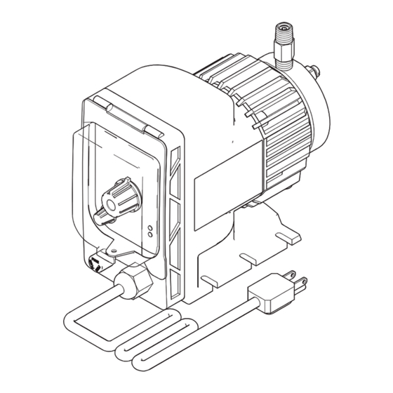
Page 6: Component Identification
. 2: Component Identification Components Supplied by Graco Prime/Bleed Valve Assembly (plastic fluid end, includes clear poly tubing) The following components are supplied by Graco: Plastic Fluid End Control Panel Motor Assembly Power Cord Inlet Valve (stainless steel fluid end) -
Page 7: Mounting And Chemical Supply Connection
Installation Mounting and Chemical Supply Injection Check Valve Connection (Plastic Fluid Section only) Connection The injection check valve is designed to prevent a back flow and to inject chemical into a piping system. This valve must be mounted within 45° of vertical (see F Failure of the diaphragm or a rupture in the fluid lines 1. -
Page 8: Typical Installation
. 4 shows two examples of an installation with a Mongoose chemical metering pump. Your installation may differ from what is shown here. The Mongoose pump (F) and the attached power cord (B) are the only components in F 4 supplied by Graco. All other components are supplied by customer. Key:... -
Page 9: Operation
Operation Operation Pressure Relief Procedure 4. Run the pump until the dispensed fluid is predomi- nately flushing fluid. Follow the Pressure Relief Procedure whenever 5. Follow the Pressure Relief Procedure. you see this symbol. Prime the Pump This equipment stays pressurized until pressure is manually relieved. -
Page 10: Adjust Feed Rate
Operation Adjust Feed Rate Adjust Stroke Length The Mongoose pump allows for the exact setting of the The stroke length can be adjusted on the Mongoose pump’s SPEED knob (H) on the pump’s control panel. pump. This is a mechanical adjustment made using See F . -
Page 11: Troubleshooting
Troubleshooting Troubleshooting 1. Follow Pressure Relief Procedure, page 9, before checking pump. Problem Cause Solution Pump does not achieve or maintain Air trapped in inlet line Straighten inlet line to eliminate high prime spots. Worn or contaminated check valves Inspect check valves in fluid end for cleanliness. - Page 12 Troubleshooting Problem Cause Solution Excessive fluid Excessive stroke rate Lower the stroke rate if adjustable on your pump. Improper stroke length Reduce stroke length. Pump will not pump System pressure too high Check system pressure to assure that it is within system-rated parame- ters of the pressure.
-
Page 13: Repair
Repair Repair Stainless Steel Fluid End Replacing the Inlet Valve Repairs 1. Follow the Pressure Relief Procedure, page 9. 2. Flush the Equipment, page 9. 3. Disconnect the power (B). 4. Close the inlet shutoff valve (C). NOTE: The following procedures apply only to models 5. -
Page 14: Plastic Fluid End Repairs
Repair Replacing the Outlet Valve Plastic Fluid End Repairs 1. Follow the Pressure Relief Procedure, page 9. 2. Flush the Equipment, page 9. 3. Disconnect the power (B). NOTE: The following procedures apply only to models 4. Close the inlet shutoff valve (C). with plastic fluid ends (A21008, A21009, A21010, A21011, A21012, A21013, A21014, A21015). - Page 15 Repair Replacing the Inlet Valve Replacing the Valve Ball Check Cartridge 1. Follow the Pressure Relief Procedure, page 9. The following procedure is the same for all plastic valve assemblies: inlet (102), outlet (103), foot (111), injection 2. Flush the Equipment, page 9. (112), and three-function (113).
- Page 16 Repair NOTICE NOTICE To ensure the proper function of the pump and to To ensure the proper function of the pump and to avoid potential damage, consider the direction of flow avoid potential damage, consider the direction of flow before inserting the ball check cartridge (114) into the before inserting each ball check cartridge (114 and valve.
-
Page 17: Parts
Parts Parts Mongoose Metering Pump Model A21000 (Stainless Steel Fluid End) shown Apply PTFE tape to threads 6 (opposite ref. 5) 4† 11‡ Mongoose Metering Pump Parts List (Stainless Steel Fluid End) Replacement Warning label is available at no cost. Ref. - Page 18 Parts Model A21008 (Plastic Fluid End) shown 6 103* (opposite ref. 5) Priming Hole 109* 104* 110* 102* Apply PTFE tape only to threads on the end of the injection Weight valve assembly. 3A4131H...
-
Page 19: Kits And Accessories
Kits and Accessories Kits and Accessories Mongoose Metering Pump Parts List (Plastic Fluid End) Ref. Part Description Part No. Description Motor assembly B32283* Pump Kit, 110 psi, 3/8 in. tubing Branding label B32284* Pump Kit, 150 psi, 3/8 in. tubing 6... -
Page 20: Dimensions
Dimensions Dimensions . 7: Mongoose Pump Dimensions 10.6 in. 7.5 in. 5.0 in. 4.13 in (26.9 cm) (19.0 cm) (12.7 cm) (10.5 cm) 3A4131H... -
Page 21: Technical Data
Technical Data Technical Data Mongoose Chemical Metering Pump Metric Maximum fluid working pressure See Models and Approvals, page 2. Maximum cycle rate (A21011 & A21015) 160 cpm Maximum cycle rate (all except A21011 & 125 cpm A21015) Input Voltage (A21016) 10.5 - 16.0 VDC Input Voltage (A21000, A21001, A21008, 95 - 135 VAC;... -
Page 22: Graco Standard Warranty
With the exception of any special, extended, or limited warranty published by Graco, Graco will, for a period of twelve months from the date of sale, repair or replace any part of the equipment determined by Graco to be defective.
Need help?
Do you have a question about the Mongoose Series and is the answer not in the manual?
Questions and answers