Table of Contents
Advertisement
Quick Links
Instructions
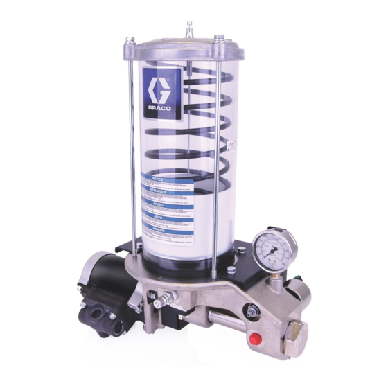
Grease or Oil A4000
Reciprocating
LubePro
For pumping non-corrosive and non-abrasive lubricants only. For professional use only.
Models: Page 2
4000 psi (27.58 MPa, 275.8 bar) Maximum Working
Pressure
Related Manuals
406900 - Air Motor Repair Kit
™
Pump
Important Safety Instructions
Read all warnings and instructions in
this manual. Save these instructions.
3A5266G
EN
Advertisement
Table of Contents

Related Manuals for Graco LubePro A4000


Summary of Contents for Graco LubePro A4000
- Page 1 Instructions Grease or Oil A4000 Reciprocating ™ LubePro Pump 3A5266G For pumping non-corrosive and non-abrasive lubricants only. For professional use only. Models: Page 2 Important Safety Instructions 4000 psi (27.58 MPa, 275.8 bar) Maximum Working Read all warnings and instructions in Pressure this manual.
-
Page 2: Table Of Contents
Remove Air Motor ..... . . 14 Graco Standard Warranty ....38 Pump Lower Disassembly . -
Page 3: Warnings
Warnings Warnings The following warnings are for the setup, use, grounding, maintenance, and repair of this equipment. The exclama- tion point symbol alerts you to a general warning and the hazard symbols refer to procedure-specific risks. When these symbols appear in the body of this manual or on warning labels, refer back to these Warnings. Product-spe- cific hazard symbols and warnings not covered in this section may appear throughout the body of this manual where applicable. - Page 4 Warnings WARNING ELECTRIC SHOCK HAZARD This equipment must be grounded. Improper grounding, setup, or usage of the system can cause electric shock. • Turn off and disconnect power at main switch before disconnecting any cables and before servicing or installing equipment. •...
-
Page 5: Installation
Installation Installation Typical Installation: Injector System (grease model pump shown) Power to Controller . 1: Typical Installation Key: Main Air Supply High Pressure Lubricant Supply Lines A1 Switched Air Supply Injector A2 Vent Valve Air Supply Lubricator Controller Filter/Regulator/Lubricator Assembly Pump Reservoir B1 - Air Filter Ground... -
Page 6: Typical Installation: Divider Valve System
Installation Typical Installation: Divider Valve System (oil model pump shown) Power to Controller . 2: Typical Installation Key: Main Air Supply A1 Switch Air Supply Line Filter/Regulator/Lubricator Assembly B1 - Air Filter B2 - Air Regulator B3 - Air Lubricator Air Solenoid Valve (3-way) Pump Module Pump Outlet... -
Page 7: Grounding
Installation Grounding Mounting Grounding is required if a low level switch and/or Mount the pump securely so that it cannot move an air valve using voltages above 30 VAC or 42 around during operation. Failure to do so could result VDC are attached to the pump. -
Page 8: Air And Fluid Line Accessories
Installation Air and Fluid Line Accessories Refer to F . 1 and F . 2, pages 5 and 6, for the follow- ing instructions. The maximum working pressure of each component in the system may not be the same. To reduce the Install the air line accessories in the order shown in F risk of over-pressurizing any part of the system, 1 and F... -
Page 9: Fill Reservoir
Installation Fill Reservoir 2. Slowly add oil (ol) until reservoir is filled to capacity . 7). Take care to not fill reservoir too quickly Oil Models and overflow the reservoir capacity. 1. Open oil fill cap (32) on the top of the reservoir. NOTE: A filter (33) is installed at the oil fill cap (32) to prevent lubricant contamination (F . -
Page 10: Priming
Installation Priming Refer to F . 1 and F . 2, pages 5 and 6, for the follow- ing instructions. Over-pressurization can result in equipment rupture and serious injury. Fill slowly to avoid over pressuriz- NOTE: ing reservoir. • Prime the pump before connecting the outlet to supply line (G). -
Page 11: Set System Pressure
Installation Pressure Relief Procedure Divider Valves 1. Check for valve operation by Follow the Pressure Relief Procedure whenever you see this symbol. using a performance indicator (shows that the valve has cycled), or, checking for lubricant dispensing at each lube point. 2. -
Page 12: Operation
Operation Operation Low Level Switch (Models 17P751 (grease) and 17P753 (oil) only) Refer to F . 1 and F . 2, pages 5 and 6, for the follow- Oil Model 17P753 ing instructions. When the oil reservoir is full, the low level float (37) sits in the high, raised position as shown in F . -
Page 13: Troubleshooting
Troubleshooting Troubleshooting Problem Cause Solution Adjust air pressure/supply. No air Pump is not operating. No lubricant Open bleed-type master air valve (F) flow. (page 5 and 6). No lubricant in reservoir Fill the reservoir. Remove trapped air (see Priming, Losing prime Pump is operating. -
Page 14: Repair
Repair Repair 5. Remove the three screws (16) and washers (59) holding air motor (1) to pump base (2). Remove air motor from pump base (F . 15). Remove Air Motor See Oil and Grease Parts, pages 18 and 20. 1. - Page 15 Repair 4. Pry the pump cylinder (11) out of the pump base (2) 10. Remove the spring pin (20) securing the piston rod . 17). (19) to the shovel rod (12). Unscrew the piston rod to separate if from the shovel rod (F .
-
Page 16: Pump Lower Reassembly
Repair 18. Inspect pump base (2) casting for scratches and 8. Apply oil resistant, thread locking compound (user scoring. If excessive damage is found, replace supplied) to threads of piston rod (19❖) and align- pump. ment rod (13❖). Screw the two rods together. Torque to 25-35 ft-lbs (34 to 47.5 N•m). - Page 17 Repair 16. Push seal retainer (9❖) into pump base (2). 17. Partially install pump cylinder (11❖) in pump base (2). 18. Lubricate o-ring (6‡❖) and install it around the shovel seal retainer (10❖) (F . 23). ‡❖ ❖ . 23 19.
-
Page 18: Parts: Grease Models
Parts: Grease Models Parts: Grease Models Part No. Description Part No. Description 17C665 PLUG, low level switch, model 25D081 MOTOR, air 17P750, 17T176, 17T193 BASE, pump SWITCH, low level, NO and NC, ✺ ‡❖ SEAL, H-wiper, 0.625 ID model 17P751, 17T177, 17T194 ‡❖... -
Page 19: Parts: Grease Models
Parts: Grease Models Parts: Grease Models 45/49 26/42 3A5266G... -
Page 20: Parts: Oil Models
Parts: Oil Models Parts: Oil Models Part No. Description Part No. Description SPACER, aluminum, 0.343I inch. 25D081 MOTOR, air 5 hex, 0.25 BASE, pump 17C665 PLUG, low level switch, model ‡❖ SEAL, H-wiper, 0.625 ID 17P752, 17T178, 17T195 ‡❖ SEAL, u-cup, quad ring, SWITCH, low level, NO and NC, ✖... -
Page 21: Parts: Oil Models
Parts: Oil Models Parts: Oil Models 3A5266G... -
Page 22: Repair Air Valve
Parts: Oil Models Repair Air Valve Disassemble the Air Valve (F . 25 and F . 26) 1. Stop pump. Relieve pressure. See Pressure Relief Procedure, page 11. 2. Perform steps 2-3 under Replace Complete Air Valve procedure. Replace Complete Air Valve 3. - Page 23 Parts: Oil Models 5. Remove the piston (302◆). Remove the u-cup seals Reassemble the Air Valve (F . 27 and F . 28) (308†◆) from each end and the detent assembly 1. Lubricate the detent cam (304◆) and install into the (303◆) and detent cam (304◆) from the center.
-
Page 24: Replace Pilot Valves
Parts: Oil Models Replace Pilot Valves Disassemble the Air Motor (F . 29) 1. Remove air motor (1) from pump base (2). See Remove Air Motor instructions, page 14. 2. Use a 10 mm socket wrench to remove four screws (211). - Page 25 Parts: Oil Models 204* *230 208* *202 202* *217 *207 209* † 208* *207 1 Apply lubricant . 29 3A5266G...
- Page 26 Parts: Oil Models Reassemble the Air Motor (F . 30 and F the cylinder. The manifold surfaces of the top and bottom covers must align. Be sure the shield (206) is in the groove on both the top and bottom covers. NOTE: For easier reassembly, start with the top cover (210) turned over on the workbench and assemble the air motor upside-down.
-
Page 27: Air Motor Installation
Parts: Oil Models Air Motor Installation 1. Align air motor (1) in pump base (2). Align pin hole in air motor with pin hole in shovel rod (12). 2. Install three washers (59) and screws (16). Torque to 5 to 10 ft.-lbs (6.77 to 13.56 N•m) (F . -
Page 28: Air Motor Parts
Air Motor Parts Air Motor Parts Ref. Description Qty. KIT, cover, bottom; includes 202 (qty 1), 24G695 203, 207, 213 (qty 1), and 217 Not sold separately. See Air Motor Seal Kit (below), Bottom Cover 202* O-RING, cover Kit (201, this table), or Top Cover Kit (210, this table) BEARING Not sold separately. -
Page 29: Air Motor Parts
Air Motor Parts Air Motor Parts *204 *230 *208 202* *202 *217 *207 209* ◆ † *208 *207 3A5266G... -
Page 30: Complete Air Valve Replacement Kit
Air Motor Parts Complete Air Valve Replacement Kit 24A351 To replace the complete air valve, order Air Valve Replacement Kit 24A351. The kit includes items 301-312 below, and items 209 and 211 on page 30.Air Valve Repair Kits Air valve parts are not sold individually. The table below shows possible kit options for each part. -
Page 31: Air Valve Parts
Air Valve Parts Air Valve Parts † 306 † 308 † 309 † 308 † 306 ti16213a 3A5266G... -
Page 32: Pump Kits Parts
Air Valve Parts Pump Kits Parts To replace the soft seals in the pump, order Soft Seal Kit 17T654. The kit includes items 3, 4, 6, 7, 8, 17, 18, and 20. To replace the hard parts and seals in the pump, order Hard Parts and Seal Kit 17T655. The kit includes items 3 - 13 and 17- 21. -
Page 33: Technical Data
Technical Specifications Technical Specifications Reciprocating Pump, Oil or Grease Metric Maximum fluid working pressure 4000 psi 27.58 MPa, 275.8 bar Pressure ratio 40:1 Pump output See Performance Curve, page 36 Reservoir capacity 12 pints oil; 6 or 12 lbs grease 5.5 L oil;... -
Page 34: Grease Pump Dimensions And Mounting
Grease Pump Dimensions and Mounting Grease Pump Dimensions and Mounting 3A5266G... -
Page 35: Oil Pump Dimensions And Mounting
Oil Pump Dimensions and Mounting Oil Pump Dimensions and Mounting 3A5266G... -
Page 36: Performance Curve
Performance Curve Performance Curve 3A5266G... -
Page 37: Notes
Notes Notes 3A5266G... -
Page 38: Graco Standard Warranty
With the exception of any special, extended, or limited warranty published by Graco, Graco will, for a period of twelve months from the date of sale, repair or replace any part of the equipment determined by Graco to be defective.
Need help?
Do you have a question about the LubePro A4000 and is the answer not in the manual?
Questions and answers