Table of Contents
Advertisement
Quick Links
Instructions-Parts
Python
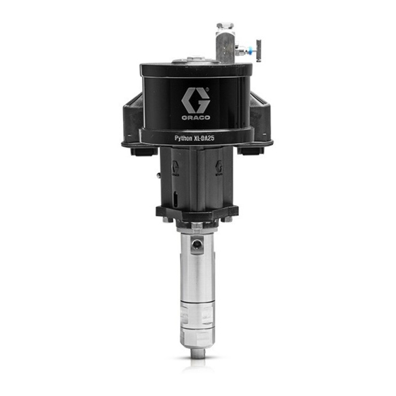
Pump
Pneumatic pump for injecting chemicals at well sites. Not for use with sour gas.
For professional use only.
Not approved for use in European explosive atmosphere locations.
See page 3 for model information, including maximum working pressures.
Important Safety Instructions
Read all warnings and instructions in this manual
before using the equipment. Save all instructions.
®
XL-DA25
3A6831G
EN
Advertisement
Table of Contents

Related Manuals for Graco A22600


Summary of Contents for Graco A22600
- Page 1 Instructions-Parts ® Python XL-DA25 Pump 3A6831G Pneumatic pump for injecting chemicals at well sites. Not for use with sour gas. For professional use only. Not approved for use in European explosive atmosphere locations. See page 3 for model information, including maximum working pressures. Important Safety Instructions Read all warnings and instructions in this manual before using the equipment.
-
Page 2: Table Of Contents
Warnings ......5 Graco Standard Warranty ....44 Installation . -
Page 3: Models
NOTE: See the Configuration Number Matrix, page 4, to find the plunger and pneumatic motor size for your unit. Pump Models Part Number Configuration Code Motor Size Lower Size Lower Coating Seal Material A22600 PCI-0600-050-075-XC-2-0 HNBR A22601 PCI-0600-050-075-XD-2-0 1/2 in. Chromex FFKM... -
Page 4: Configuration Number Matrix
Configuration Number Matrix Configuration Number Matrix Check the identification plate (ID) for the 17-digit Configuration Number of your pump. Use the following matrix to define the components of your pump. NOTE: Not all combinations are possible. Sample Configuration Number: PCI-0600-075-113-XC-2-0 0600 Pneumatic Pneumatic... -
Page 5: Warnings
Warnings Warnings The following warnings are for the setup, use, grounding, maintenance, and repair of this equipment. The exclama- tion point symbol alerts you to a general warning and the hazard symbols refer to procedure-specific risks. When these symbols appear in the body of this manual or on warning labels, refer back to these Warnings. Product-specific hazard symbols and warnings not covered in this section may appear throughout the body of this manual where applicable. - Page 6 Warnings PERSONAL PROTECTIVE EQUIPMENT Wear appropriate protective equipment when in the work area to help prevent serious injury, including eye injury, hearing loss, inhalation of toxic fumes, and burns. Protective equipment includes but is not limited to: • Protective eyewear, and hearing protection. •...
-
Page 7: Installation
Installation Installation Required Accessories Install the following required accessories as shown in . 1, using adapters as necessary. If using a flammable gas to drive the motor, to reduce the risk of fire or explosion, route the exhaust away Pneumatic Line from all sources of ignition. -
Page 8: Typical Installation
7.) The Python XL-DA25 pump (F) and secondary bleed-type pneumatic valve (B) are the only components in F . 1 supplied by Graco. All other com- ponents are supplied by customer. The pump can be bolted to a wall or skid by the attached Key: bracket. -
Page 9: Connect Pneumatic Supply
NOTE: A pressure relief valve is required and is avail- able from Graco, and can be connected back to the tank Minimum pneumatic pressure can be found by first find- or directly to the inlet side of the pump. See Kits and ing the table that corresponds to the pneumatic motor Accessories on page 36. - Page 10 Installation Minimum Pneumatic Pressures by Fluid Plunger Size and Outlet Pressures Actual running pressure must be set in field to avoid stalling. See Performance Charts, starting on page 40, for max- imum flows at any given pressure. 0600 (6.0 in) Pneumatic Motor Minimum Gas Pressure psi (MPa, bar) Outlet Pressure psi 1/2 Inch...
- Page 11 Installation 0750 (7.5 in) Pneumatic Motor Minimum Gas Pressure psi (MPa, bar) Outlet Pressure psi 3/4 Inch 1 Inch (MPa, bar) Fluid Plunger Fluid Plunger 0 (0, 0) 15.0 (0.1, 1.0) 15.0 (0.1, 1.0) 500 (3.4, 34.5) 15.0 (0.1, 1.0) 15.0 (0.1, 1.0) 1000 (6.9, 68.9) 15.0 (0.1, 1.0)
-
Page 12: Operation
Operation Operation Pressure Relief Procedure Flush the Equipment Follow the Pressure Relief Procedure whenever you see this symbol. This equipment stays pressurized until pressure is To avoid fire and explosion, always ground equipment manually relieved. To help prevent serious injury from and waste container. -
Page 13: Prime The Pump
Operation Prime the Pump Calibrate Chemical Dosage 1. Verify all connections and fluid lines are tight. 1. Set the pump to an estimated setting of the flow rate. NOTE: The pneumatic pressure regulator (E) and speed control valve (R) (needle valve) both affect the pump 2. -
Page 14: Maintenance
Maintenance Maintenance Preventive Maintenance Schedule The operating conditions of your particular pump deter- mines how often maintenance is required. Establish a preventive maintenance schedule by recording when and what kind of maintenance is needed, and then determine a regular schedule for checking your pump. Tighten Threaded Connections Check that all threaded connections are tight before each use and at routine intervals. -
Page 15: Troubleshooting
Troubleshooting Troubleshooting 1. Follow Pressure Relief Procedure, page 12, before checking or repairing pump. 2. Check all possible problems and causes before dis- assembling pump. Problem Cause Solution Air bubbles in fluid. Fluid inlet line is loose. Tighten. Fluid leaking. Loose fittings. -
Page 16: Repair - Pump Lower
• Always use Genuine Graco Parts and Accessories, available from your Graco distributor. If you supply your own accessories, be sure they are adequately sized and pressure rated for your system. Disconnect the Pump Lower Threads are very sharp. -
Page 17: Pump Repair
Repair - Pump Lower 7. Use a hammer and brass rod to loosen the jam Pump Repair nut (119). Unscrew the jam nut as far as possible. 1. Remove the lower fluid cylinder (113) and cylinder cap (117) assembly from the primary fluid cylinder (101). - Page 18 Repair - Pump Lower Primary Secondary Seal Stack (102) Seal Stack (107) 9. Install the new primary seal stacking (102) including bearing (103). Use grease during installation. 10. Install the packing nut (106) with pipe sealant until finger tight. 5. Remove the plunger check valve seat (112) and plunger check valve poppet (110).
-
Page 19: Reconnect The Pump Lower
Repair - Pump Lower 12. Install two new o-rings (118) on the lower fluid cylin- der (113). Orientation does not matter for this part. 13. Apply anti-seize compound to both lower fluid cylin- der (113) threads and install into the fluid cylinder (101). -
Page 20: Repair - Pneumatic Motor
Repair - Pneumatic Motor Repair - Pneumatic Motor Replace Seals or Rebuild Pneumatic Valve Inspect and replace seals and worn parts while disas- sembling and reassembling the pneumatic valve on the next following pages. Pneumatic Valve Use F . 12 and the following table to identify the kits needed for replacements: Replace Complete Pneumatic Valve 1. - Page 21 Repair - Pneumatic Motor 310 †321 307 304 303 311 312 313 305 †308 302 †309 †308 307 †321 Apply lubricant. 310 ti16213a . 12 3A6831G...
- Page 22 Repair - Pneumatic Motor Reassemble the Pneumatic Valve 7. Install the spring (311). Lubricate and install the pneumatic valve cup (312), see F . 14. Align the 1. See F . 12. Lubricate detent cam (304) and small round magnet with the pneumatic inlet. install into housing.
-
Page 23: Replace Pilot Valves
Repair - Pneumatic Motor Replace Pilot Valves 4. Slide the drip shield (4) down on the tie rods (3). 1. Stop the pump. Follow the Pressure Relief Proce- dure, page 12. 2. Disconnect the pneumatic line to the motor. 3. Loosen the screw (16) and remove the tie rod shield (15). -
Page 24: Repair Pneumatic Motor
Repair - Pneumatic Motor Repair Pneumatic Motor NOTE: Pneumatic Motor Seal Kits are available. See Pneumatic Motor Parts List, page 35, for the correct kit for your motor. For best results, use all parts in the kit. Disconnect the Pneumatic Motor 1. - Page 25 Repair - Pneumatic Motor Disassemble the Pneumatic Motor Reassemble the Pneumatic Motor 1. Use a 10 mm socket wrench to remove the four NOTE: For easier reassembly, start with the top screws (218), and remove the pneumatic valve cover (213) turned over on the workbench and assem- (217) and gasket (216).
- Page 26 Repair - Pneumatic Motor 11. Carefully place the bottom cover (201) on the cylin- Reconnect the Pneumatic Motor der (211), sliding the rod (206) through the bearing 1. Replace the motor on the mounting bracket (2). (202). The manifold surfaces of the top and bottom covers must align.
- Page 27 Repair - Pneumatic Motor 3A6831G...
-
Page 28: Parts
Parts Parts Python XL-DA25 Pneumatic Pump PCI-0750-050-075-XC-2-0 shown 32 3A6831G... - Page 29 Parts Python XL-DA25 Pump Parts List Ref. Part Description Ref. Part Description B33109 Safety valve, 110 PSI B33007 Pneumatic motor, 6.0 in.; PCI-0600-xxx-xxx-xx-2-x B33110 Pipe bushing fitting, 1 in. x 1/4 in. npt; (pack of 1) B33008 Pneumatic motor, 7.5 in.; PCI-0750-xxx-xxx-xx-2-x 131295 Needle valve...
-
Page 30: Pump Lower
Parts Pump Lower 3A6831G... - Page 31 Parts Pump Lower Parts List PCI-xxxx-050-075-xx-2-x PCI-xxxx-075-113-xx-2-x PCI-xxxx-100-138-xx-2-x Ref. Description 1/2 in. Part numbers 3/4 in. Part numbers 1 in. Part numbers Fluid cylinder B33173 B33138 B33139 Primary seal stack See table below Primary bearing B33174 B33136 B33137 Pellet (included with ref. 101) Packing nut shim B33175 B33134...
-
Page 32: Pneumatic Motor Parts
Parts Pneumatic Motor Parts PCI-0600, 6.0 in. (152.4 mm); PCI-0750, 7.5 in. (190.5 mm), shown ‡ These items are only available in Pneumatic Motor Kits B32251 and B32770 3A6831G... - Page 33 Parts Pneumatic Motor Parts List Part number shown: B33007 (PCI-0600): 6.0 in. (152.4 mm) B33008 (PCI-0750): 7.5 in. (190.5 mm) Ref. Part Description Ref. Part Description Manifold gasket; (included with ref. 214 B33171 Lower cover; PCI-0600 215, 24A580) B33172 Lower cover; PCI-0750 24A580 Motor manifold Bearing;...
-
Page 34: Pneumatic Valve Parts
Parts Pneumatic Valve Parts ti16213a 3A6831G... - Page 35 Parts Pneumatic Valve Parts Complete Pneumatic Valve Replacement Kit B33164 To replace the complete pneumatic valve, order Pneumatic Valve Replacement Kit B33164 (6 in. and 7 in.). The kit includes items 301-312 below, and items 209 and 211 on page 33. Pneumatic Valve Repair Kits Pneumatic valve parts are not sold individually.
-
Page 36: Kits And Accessories
Kits and Accessories Kits and Accessories Pump Lower Models Additional Kits & Accessories Part No. Description Configuration Lower Lower Seal B32045 225-750 PSI Pressure Relief Valve Kit Part No. Code Size Coating Material (Adjustable) B33010 050-075-XC-2 HNBR B32046 750-1500 PSI Pressure Relief Valve Kit B33011 050-075-XD-2 1/2 in. -
Page 37: Dimensions
Dimensions Dimensions Python XL-DA25 Pump Dimensions . 22 Python Pump Dimensions Size 24.0 in. 14.5 in. 16.75 in. 17.75 in. 8.0 in. (61.0 cm) (36.8 cm) (42.5 cm) (45.1 cm) (20.3 cm) 24.0 in. 14.5 in. 16.75 in. 17.75 in 8.0 in. -
Page 38: Wall Bracket Mounting Hole Diagram
Dimensions Wall Bracket Mounting Hole Diagram 2.79 2.79 2.00 2.00 4X R 0.175 4X Ø .400 2X 1.000 2X 8.59 2X 2.375 4X 6.936 2X 1.09 4X 1.14 2X 5.50 2X 11.00 3A6831G... -
Page 39: Pneumatic Mounting Hole Diagrams
Dimensions Pneumatic Mounting Hole Diagrams PCI-0600 (6 in. motor) Three 5/8-11 tie rod holes 5.906 in. (150 mm) bolt circle Two M8 mounting holes 2.0 in. (50 mm) 5.250 in. ti12738a (133 mm) Four M8 X 1.25 optional mounting holes ti12737a 3.38 in. -
Page 40: Performance Charts
Performance Charts Performance Charts 6 in. Motors 1/2 in. Plunger (PCI-0600-050) Air Consumption Inlet Pressure - (SCFM) PSI (MPa, Bar) A-15 (0.10, 1.0) (1893) B-25 (0.17, 1.7) C-50 (0.34, 3.4) D-75 (0.52, 5.2) (1514) E-100 (0.69, 6.9) --- Fluid Flow - - Air Flow (1136) Pump Speed... -
Page 41: In. Motors
Performance Charts 1 in. Plunger (PCI-0600-100) Inlet Pressure - Air Consumption PSI (MPa, Bar) (SCFM) A-15 (0.10, 1.0) 1800 B-25 (0.17, 1.7) (6814) C-50 (0.34, 3.4) 1600 D-75 (0.52, 5.2) (6057) E-100 (0.69, 6.9) 1400 (5300) --- Fluid Flow 1200 - - Air Flow (4542) 1000... - Page 42 Performance Charts 1 in. Plunger (PCI-0750-100) Inlet Pressure - Air Consumption PSI (MPa, Bar) (SCFM) A-15 (0.10, 1.0) B-25 (0.17, 1.7) 1800 C-50 (0.34, 3.4) (6814) D-75 (0.52, 5.2) 1600 E-100 (0.69, 6.9) (6057) 1400 --- Fluid Flow (5300) - - Air Flow 1200 (4542) 1000...
-
Page 43: Technical Specifications
Technical Specifications Technical Specifications Python XL-DA25 Chemical Injection Pump ........Metric Maximum pneumatic inlet pressure See Models on page 3. -
Page 44: Graco Standard Warranty
With the exception of any special, extended, or limited warranty published by Graco, Graco will, for a period of twelve months from the date of sale, repair or replace any part of the equipment determined by Graco to be defective.
Need help?
Do you have a question about the A22600 and is the answer not in the manual?
Questions and answers