Table of Contents
Advertisement
Quick Links
Instructions
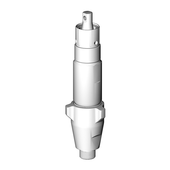
Displacement Pump
For use with Reactor
3500 psi (24.5 MPa, 245 bar) Maximum Working Pressure
See page 2 for model information.
Important Safety Instructions
Read all warnings and instructions in
this manual before using the
equipment. Save these instructions.
®
air and electric proportioners. For professional use only.
309577ZAA
ti3733
EN
TI2663
Advertisement
Table of Contents

Subscribe to Our Youtube Channel
Related Manuals for Graco AGP-U100


Summary of Contents for Graco AGP-U100
- Page 1 Instructions Displacement Pump 309577ZAA ® For use with Reactor air and electric proportioners. For professional use only. 3500 psi (24.5 MPa, 245 bar) Maximum Working Pressure See page 2 for model information. Important Safety Instructions Read all warnings and instructions in this manual before using the equipment.
-
Page 2: Table Of Contents
Graco Standard Warranty ....36 Manual in English Description Graco Information ......36 309551 or 312065... -
Page 3: Warnings
Warnings Warnings The following warnings are for the setup, use, grounding, maintenance, and repair of this equipment. The exclamation point symbol alerts you to a general warning and the hazard symbols refer to procedure-specific risks. When these symbols appear in the body of this manual or on warning labels, refer back to these Warnings. Product-specific hazard symbols and warnings not covered in this section may appear throughout the body of this manual where applicable. - Page 4 Warnings WARNING EQUIPMENT MISUSE HAZARD Misuse can cause death or serious injury. • Do not operate the unit when fatigued or under the influence of drugs or alcohol. • Do not exceed the maximum working pressure or temperature rating of the lowest rated system component.
- Page 5 Warnings WARNING TOXIC FLUID OR FUMES HAZARD Toxic fluids or fumes can cause serious injury or death if splashed in the eyes or on skin, inhaled or swallowed. • Read Safety Data Sheet (SDS) for handling instructions and to know the specific hazards of the fluids you are using, including the effects of long-term exposure.
-
Page 6: Important Isocyanate (Iso) Information
Important Isocyanate (ISO) Information Important Isocyanate (ISO) Information Isocyanates (ISO) are catalysts used in two component materials. Isocyanate Conditions Spraying or dispensing fluids that contain isocyanates creates potentially harmful mists, vapors, and atomized particulates. • Read and understand the fluid manufacturer’s warnings and Safety Data Sheet (SDS) to know specific hazards and precautions related to isocyanates. -
Page 7: Keep Components A And B Separate
Important Isocyanate (ISO) Information Keep Components A and B Foam Resins with 245 fa Separate Blowing Agents Some foam blowing agents will froth at temperatures above 90°F (33°C) when not under pressure, especially if agitated. To reduce frothing, minimize preheating in a circulation system. -
Page 8: Repair
Repair Repair Pressure Relief Procedure 3. Shut off feed pumps and agitator, if used. 4. Turn PRESSURE RELIEF/SPRAY valves (ASA, SB) Follow the Pressure Relief Procedure whenever to PRESSURE RELIEF. Route fluid to waste you see this symbol. containers or supply tanks. Ensure that gauges drop to 0. -
Page 9: Fill The Wet-Cups
Turn main power OFF before filling wet cup. 1. Component A (ISO) Pump: Keep reservoir (R) 3/4 filled with Graco Throat Seal Liquid (TSL), Part No. 206995. Wet-cup piston (28) circulates TSL through packing nut/wet-cup (19), to carry away isocyanate TI3765a film on displacement rod. -
Page 10: Cutaway Views
Repair Cutaway Views Component A (ISO) Pump 25P857 246831 246830 25P944 25P858 246832 24Y175 19† 19† †*22 †*22 24*† 24*† †28 †28 †25 26*† †25 26*† 27*† 27*† ‡*8 ‡*8 ti3734b ti3734c ti40680a 309577ZAA... - Page 11 Repair Component B (Resin) Pump 245971 245970 24Y174 245972 18D010 † † ‡*8 ‡*8 TI2668C TI2668b 309577ZAA...
-
Page 12: Disassemble The Pump
Repair Disassemble the Pump 10. Push the retaining spring (E) up. Push the pin (F) out. Loosen the star-shaped locknut (G) by hitting firmly with a non-sparking hammer. Unscrew the pump. Pump rod and connecting rod move during operation. Moving parts can cause serious injury such as pinching or amputation. - Page 13 Repair 11. Remove the packing wet-cup as follows: 12. Loosen the intake valve housing (5) with a non-sparking hammer, then unscrew. Remove the a. Component A (ISO) Pumps: o-ring (15). Remove the packing wet-cup assembly. Compress the piston (28) into the wet-cup (19), using a 1/2 in.
- Page 14 Repair 15. Using a screwdriver in the groove (H), remove hte 17. Unscrew the piston (7) from the rod (1). Remove the sleeve (4) from the cylinder (2), or pull it off of the ball (16), u-cup (13), and bushing (14). rod.
-
Page 15: Reassemble The Pump
Repair Reassemble the Pump 3. Install the throat u-cup as follows: a. Models 246831, 246832, 245971, 245972, NOTE: Coat all non-thread sealed parts with ISO Pump 24Y174, 18D010, 25P857, 25P858, 25P944, Oil before reassembly, to ease future disassembly. and 24Y175: Grease the u-cup (20*) and 1. - Page 16 Repair a. Component A (ISO) Pump: NOTE: The groove (H) in the sleeve outer surface must be toward the bottom. • Install spring (25) in the wet-cup (19). • Install o-rings (24*, 26*) on the piston (28) and 6. Lubricate the piston u-cup and sleeve top edge. insert the piston in the wet-cup.
- Page 17 Repair 9. Reassemble the intake valve with o-ring (10*), seat Model Torque (9), and ball (11*). Install ball guide (12). ft-lb (N•m) 246830, 245970, 18D010, and 65-75 (88-101) Models 246832, 18D010, 25P857, 25P858, 25P857 25P944, and 245972 only: Install spring (8*) with screw at top.
- Page 18 Repair NOTE: Steps 15-18 apply to pump B. See F . 3. To 16. Continue screwing the pump into the housing until reconnect pump A, go to step 19. the fluid outlet (D) is aligned with the steel tube and top threads are +/- 1/16 in.
- Page 19 Repair NOTE: Steps 19-32 apply to pump A only. See F . 4. 24. Apply thread sealant and screw the barbed fitting into the motor side of the wet-cup. Torque to 10-15 19. Screw the pump into the bearing housing (M) until ft-lb (14-20 N•m).
-
Page 20: Parts
Parts Parts Component A (ISO) Pumps, with wet-cup flush feature Part 246830 E-20 and E-XP1; includes items 1-7, 9-28 Part 246831 E-XP2 and A-25; includes items 1-7, 9-22, 24-28 Part 246832 E-30; includes items 1-17, 19-22, 24-28 (shown) Part 24Y175 A-XP1;... - Page 21 Parts Qty. Ref. Part Description 246830 246831 246832 24Y175 25P857 25P858 25P944 240518 ROD, displacement; sst 240517 ROD, displacement; sst 246689 ROD, displacement; sst 15H110 ROD, displacement; sst 243346 CYLINDER, pump 243347 CYLINDER, pump 245413 CYLINDER, pump 17F955 CYLINDER, pump 108526 O-RING;...
- Page 22 Parts Qty. Ref. Part Description 246830 246831 246832 24Y175 25P857 25P858 25P944 15B078 BUSHING, piston 15J197 BEARING, lower 15B079 BUSHING, piston 17F958 BEARING, lower 156593 O-RING; BUNA-N 156633 O-RING; BUNA-N 160325 O-RING; BUNA-N 105444 BALL, piston; sst; 0.3125 in. (8 101947 BALL, piston;...
- Page 23 Parts * Parts included in Pump Repair Kits (purchase Pump Part Pump Repair Kit Wet-Cup Kit separately). Some parts in the kit may not be used in 246830 246420 246962 your pump. 246831 15C851 246963 Parts included in Wet-Cup Kits. Order the correct kit for †...
- Page 24 Parts Component A Pump Repair Kits 15C851 107098 107563 108526 103414 110955 156633 ti34356a 309577ZAA...
- Page 25 Parts 246420/17K351 15C852 107079 C20111 108822 108526 111178 107098 156593 160325 107563 118380 118403 118381 ti34359a 309577ZAA...
- Page 26 Parts 17K352 246420 107079 107563 108526 118380 108526 156593 156593 107563 118381 118380 118381 107079 ti40682a 309577ZAA...
- Page 27 Parts 18E195 18E250 18E249 108526 107098 108822 107079 108526 107098 156593 156633 160325 118380 110955 107563 C20111 103414 111178 ti40683a 309577ZAA...
- Page 28 Parts Component B (Resin) Pumps Part 245970 E-20 and E-XP1; includes items 1-7, 9-23 Part 245971 E-XP2 and A-25; includes items 1-7, 9-22 Part 245972 E-30; includes items 1-22 (shown) Part 24Y174 A-XP1; includes items 1-7, 9-22 Part 18D010 Reactor 3 E-20; includes items 1-17, 19-22 NOTE: These pumps were also used on Component A (ISO) side of Reactors built before May 2003.
- Page 29 Parts Qty. Ref. Part Description 245970 245971 245972 24Y174 18D010 240518 ROD, displacement; sst 240517 ROD, displacement; sst 246689 ROD, displacement; sst 15H110 ROD, displacement; sst 243346 CYLINDER, pump 243347 CYLINDER, pump 245413 CYLINDER, pump 17F955 CYLINDER, pump 108526 O-RING; PTFE 107098 O-RING;...
- Page 30 Parts Qty. Ref. Part Description 245970 245971 245972 24Y174 18D010 105444 BALL, piston; sst; 0.3125 in. (8 mm) 101947 BALL, piston; sst; 0.375 in. (10 mm) 107203 BALL, piston; sst; 0.5625 in. (14 mm) 15B075 BUSHING, rod 15B074 BUSHING, rod 15B076 BUSHING, rod 15J196...
- Page 31 Parts Component B Pump Repair Kits 246422 246421 18E196 108822 107098 108526 107079 108526 107098 156593 156633 160325 ti33336b 309577ZAA...
- Page 32 Parts 17K352 246420 107079 108526 108526 156593 156593 107079 107563 118380 118381 ti34358a 309577ZAA...
-
Page 33: Accessories
Accessories Accessories Wet-Cup Conversion Kits These kits convert 245970, 245971, or 245972 pumps to the wet-cup flush design. Refer to the following table to select the correct kit for your pump. Kits include a Pump Wet-cup Flush Kits manual. Part Wet-Cup Conversion Kit 245970, 24Y174 248061, includes:... -
Page 34: Technical Specifications
Technical Specifications Technical Specifications Displacement Pump Metric Maximum fluid working pressure 3500 psi 24.5 MPa, 245 bar Effective Area of Displacement Models 246830, 245970, 24Y174, 24Y175, 0.396 in. 2.55 cm 18D010, 25P857 Models 246831, 245971, 25P858 0.522 in. 3.56 cm Models 246832, 245972, 25P944 0.743 in. - Page 35 Technical Specifications California Proposition 65 CALIFORNIA RESIDENTS WARNING: Cancer and reproductive harm – www.P65warnings.ca.gov. 309577ZAA...
-
Page 36: Graco Standard Warranty
With the exception of any special, extended, or limited warranty published by Graco, Graco will, for a period of twelve months from the date of sale, repair or replace any part of the equipment determined by Graco to be defective.
Need help?
Do you have a question about the AGP-U100 and is the answer not in the manual?
Questions and answers