Table of Contents
Advertisement
Quick Links
Instructions, Repair and Parts
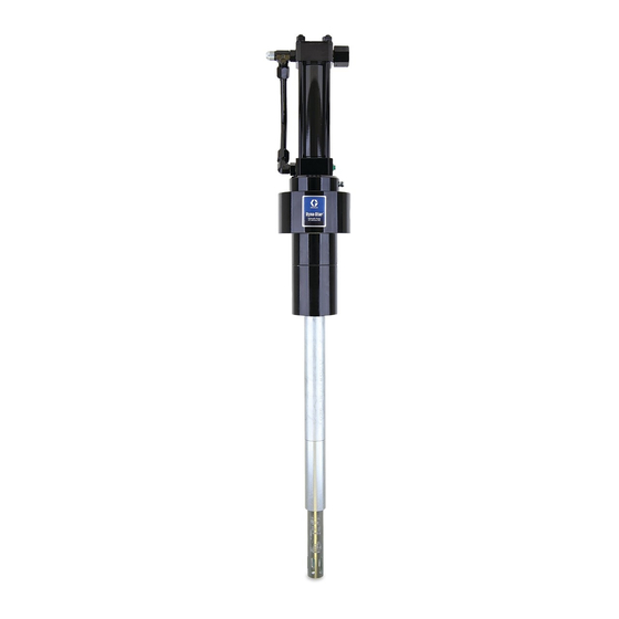
Dyna-Star
Hydraulic Reciprocator and
High Pressure Pump
High Pressure Pump and Reciprocator used for dispensing grease in wire-
line applications for oil well services.
900 psi (6.2 MPa, 62.1 bar)) Maximum Hydraulic Input Pressure
10,000 psi (69 MPa, 689 bar) Maximum Fluid Outlet Pressure
Model 25A189: 120 lb Drum Length
Important Safety Instructions
Read all warnings and instructions in this manual.
Save these instructions.
®
3A3005C
EN
Advertisement
Table of Contents

Related Manuals for Graco Dyna-Star 25A189


Summary of Contents for Graco Dyna-Star 25A189
- Page 1 Instructions, Repair and Parts ® Dyna-Star Hydraulic Reciprocator and 3A3005C High Pressure Pump High Pressure Pump and Reciprocator used for dispensing grease in wire- line applications for oil well services. 900 psi (6.2 MPa, 62.1 bar)) Maximum Hydraulic Input Pressure 10,000 psi (69 MPa, 689 bar) Maximum Fluid Outlet Pressure Model 25A189: 120 lb Drum Length Important Safety Instructions...
- Page 2 Warnings Warnings The following warnings are for the setup, use, grounding, maintenance, and repair of this equipment. The exclama- tion point symbol alerts you to a general warning and the hazard symbols refer to procedure-specific risks. When these symbols appear in the body of this manual or on warning labels, refer back to these Warnings. Product-specific hazard symbols and warnings not covered in this section may appear throughout the body of this manual where applicable.
- Page 3 Warnings WARNING WARNING WARNING EQUIPMENT MISUSE HAZARD Misuse can cause death or serious injury. • Do not operate the unit when fatigued or under the influence of drugs or alcohol. • Do not exceed the maximum working pressure or temperature rating of the lowest rated system component.
-
Page 4: Typical Installation
The following Typical Installation is only provided as a guide for selecting and installing system components and accessories. Mount pump to suit the type of installation planned. For assistance in designing a system to suit your needs, contact your Graco Distributor. Key:... - Page 5 To reduce the risk of serious injury including fluid minimum 3/4 inch return line (F) on the reciprocator. injection and splashing in the eyes or on the skin Contact your Graco representative for details of line siz- which may be caused if component ruptures, all ing.
- Page 6 Installation Grounding Grounding the Pump (F . 1) To ground pump: 1. Remove ground screw (Z) and insert through eye of ring terminal at end of ground wire. 2. Fasten ground screw back onto pump and tighten The equipment must be grounded to reduce the risk securely.
-
Page 7: Operation
Operation Operation Before Starting Pump Pressure Relief Procedure COMPONENT RUPTURE HAZARD Follow the Pressure Relief Procedure whenever Overpressurizing any component can result in seri- you see this symbol. ous injury or property damage as a result of rupture, fire, and/or explosion.The maximum working pres- sure of each component in the system may not be the same. -
Page 8: Starting Pump
Operation Starting Pump If the Pump Leaks at the Fluid Fittings 1. Turn on hydraulic power supply. Tighten fittings (1, 5, 60) which are self-sealing and 2. Open return line shut-off valve (H) first, then slowly have replaceable o-rings. If leaking persists, change open the hydraulic supply shut-off valve (L). -
Page 9: Troubleshooting
Troubleshooting Troubleshooting Problem Cause Solution Pump does not run. Closed dispense valve. Pump only runs with valve open. Hydraulic supply pressure too low - Increase supply pressure using a see gauge (M). pressure adjusting valve. Insufficient hydraulic fluid supply. Check hydraulic supply. Adjust to a maximum of 3 gpm (11 lpm) flow. - Page 10 Service Service Removing Displacement Pump from Reciprocator NOTE: The reference letters used in the following Ser- vice instructions refer to the Typical Installation illustra- Disassembly tion provided on page 4. The reference numbers used in the following Service instructions refer to the Parts pages beginning on page Pump Leaks at the Fluid Fittings Tighten fittings (1, 5, 60;...
- Page 11 Service 7. Use a strap wrench on spacer tube (114) to unscrew Disassembly it out of the pump adapter (8) and slide it down as 1. Relieve pressure, page 7. far as it will go (F . 5). 2. Disconnect reciprocator from displacement pump (see Removing Displacement Pump from Recipro- cator, page 10).
- Page 12 Service 4. Remove retainer nut (11) and seal (44) from top of pump adapter (8). 7. Use a wrench to loosen elbow (1) and tee (60). Remove fluid tube (45). Install plug in each fitting to 5. Remove four capscrews (46) and washers (52) from prevent contamination (F .
- Page 13 Service 8. Check o-rings (1a and 60a) on fittings (1 and 60) Reassembly and replace them if they are worn or damaged. Use Kit 247455. Use all new parts included in the kit. 1. Install seal (16) in bottom of cylinder cap (32) in the orientation shown in F .
- Page 14 Service 3. Install seal (44) on retainer nut (11). Install retainer 5. Install lock washers (37) and nuts (36) onto tie rods nut in pump adapter (8) (F . 14). Torque retainer (38). Torque nuts to 28-32 ft-lbs (38-43 N.m) (F nut to 54 to 56 ft-lbs (73-75 N.m).
-
Page 15: Reciprocator Repair
Reciprocator Repair Reciprocator Repair • Clean and inspect all parts for wear or damage. Replace worn parts as needed. For best results, always replace all the o-rings and seals when you disassemble the pump. Repair Kit 247455 is avail- able. Parts included in the kit are marked with an asterisk, for example (23*), in the text and drawings. - Page 16 Reciprocator Repair 5. Place bottom cap (32) in vise. Remove four cap- 9. Use a rubber or plastic head mallet to tap the bot- screws (46) and lockwashers (52). tom of the displacement rod (35) and loosen cylin- der (25). 10.
- Page 17 Reciprocator Repair 13. Visually inspect the spring (21). If there is wear or damage, remove nut (18), spring (21) and retainers (20) from the trip rod (12) (F . 22). . 23 2. Thread nut (18) onto rod until it runs out of thread so that it bottoms out on the rod’s shoulder (F .
- Page 18 Reciprocator Repair 9. Use a spanner wrench to screw piston (22) onto NOTE: When attaching the motor housing (43) onto the displacement rod (34). Torque to 40 to 48 ft-lb (54 to bottom cylinder cap (32), be sure that the adapter (72) in 65 N.m).
-
Page 19: Displacement Pump Repair
Reciprocator Repair 17. If tie rods (38) were removed, reinstall them with Displacement Pump Repair short threaded end up. The other end should be screwed about 9/16” into bottom cylinder cap (32). Disassembly When reinstalling cylinder (25), be sure port in top cylin- •... - Page 20 Reciprocator Repair Reassembly Reassembling Displacement Pump to Reciprocator 1. Clean all the parts in a compatible solvent and inspect them for wear or damage. Use all parts in the repair kit, replace other parts as necessary. 1. Clamp reciprocator in vise. 2.
- Page 21 Reciprocator Repair 4. Screw connecting rod (107) into displacement rod 6. Use a strap wrench to screw together shovel tube (35) until holes align. Install cotter pin (204) through (117) and pump cylinder (109). holes. 7. Connect hydraulic supply and return hoses to fit- tings (5, 60).
- Page 22 Parts Parts Displacement Pump Model 25A191: 120# Drum Length Part No. Description 17J113 PISTON 196185 WASHER, retainer 104† 114171 PACKING, u-cup 106† 100065 BALL 25A142 ROD, connecting 192540 ROD, shovel 25A165 CYLINDER, pump 110† 25A167 GASKET, seal 111† 192534 BEARING 112†...
- Page 23 Parts † † † † † † Assembled / Cutaway View Using nut (113), torque the pump cylinder 109 to the extension tube (114) at 45 to 55 ft-lb (61 to 75 N.m). Torque the shovel rod (108) to the piston (102) at 25 to 30 ft-lb (34 to 41 N.m). Torque the piston (102) to the extension rod (107) at 25 to 30 ft-lb (34 to 41 N.m).
- Page 24 Parts Parts Reciprocator Model 25A190 Ref. Part No. Description Qty. 100133 LOCKWASHER, 3/8” Ref. ROD, tie, 8.5” shoulder to shoul- Part No. Description Qty. 187405 der, 3/8-16 unc-2a, cs 155685 O-RING ELBOW, straight thread, 3/4-16 40 128583 LABEL, Warning 106470 unf-2a x 3/4-16 unf-2a, 37°...
- Page 25 Parts Torque to 276-324 in-lbs (31-37 N.m) Torque to 40-48 ft-lbs (54-65 N.m) Torque to 42-45 in-lbs (4-5 N.m). Torque to 28-32 ft-lbs (38-43 N.m). Torque to 54-56 ft-lbs (73-76 N.m). Assemble with lips facing up. Torque to 54-56 in-lbs (6.0-6.5 N.m). Assemble with lips facing down.
- Page 26 Parts Parts Pump Model 25A189: 120# Drum Length Ref No. Part No. Description RECIPROCATOR, page 24 202* 25A168 SEAL, gasket 108513 DISPLACEMENT PUMP 183741 LABEL, identification 207* 160742 PELLET, nylon These parts are included in Kit 247455 (purchase separately). See page 24 for other parts included in this kit.
-
Page 27: Technical Data
Technical Data Technical Data Dyna-Star Hydraulic Reciprocator and High Pressure Pump Metric Maximum grease output pressure 10,000 psi 69 MPa, 689 bar Hydraulic supply inlet 3/4 inch - 16 JIC (37° flare) Hydraulic return outlet 3/4 inch NPT Fluid outlet Adapter 1/2 inch NPT female Pump body... - Page 28 Technical Data Typical Fluid Outlet Pressure 3A3005C...
-
Page 29: Dimensions And Mounting Hole Layout
Technical Data Dimensions and Mounting Hole Layout 3/4” - 16 JIC 3/4 NPT Hydraulic Outlet 3.53 (89.6mm) 37° flare (m) minimum diameter clearance hole 3.536 in. (90.424 mm) 1/8 NPT throat seal weep port 1/2 NPT female fluid outlet adapter 3.536 in. -
Page 30: Graco Standard Warranty
With the exception of any special, extended, or limited warranty published by Graco, Graco will, for a period of twelve months from the date of sale, repair or replace any part of the equipment determined by Graco to be defective.
Need help?
Do you have a question about the Dyna-Star 25A189 and is the answer not in the manual?
Questions and answers