Advertisement
Quick Links
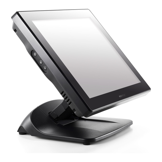
XT-5315/5515/5515Pro
P-CAP Touch Terminal
User Manual
Package Contents
15" P-CAP touch terminal with Gen 7E or Gen 8E base................(x 1)
Power adapter..................................................................(x 1)
Power cord.....................................................................(x 1)
User manual....................................................................(x 1)
FCC NOTES
This equipment has been tested and found to comply with the limits for a Class A digital
device, pursuant to part 15 of the FCC Rules. These limits are designed to provide
reasonable protection against harmful interference when the equipment is operated in a
commercial environment. This equipment generates, uses, and can radiate radio frequency
energy and, if not installed and used in accordance with the instruction manual, may cause
harmful interference to radio communications. Operation of this equipment in a residential
area is likely to cause harmful interference in which case the user will be required to correct
the interference at his own expense.
This device complies with part 15 of the FCC Rules. Operation is subject to the following
two conditions: (1) This device may not cause harmful interference, and (2) this device must
accept any interference received, including interference that may cause undesired operation.
CE CLASS A WARNING
This equipment is compliant with Class A of CISPR 32. In a residential environment this
equipment may cause radio interference.
WARRANTY LIMITS
Warranty will terminate automatically when the machine is opened by any person other than
the authorized technicians. The user should consult his/her dealer for the problem happening.
Warranty voids if the user does not follow the instructions in application of this merchandise.
The manufacturer is by no means responsible for any damage or hazard caused by improper
application.
警告使用者
此為甲類資訊技術設備,於居住環境中使用時,可能會造成射頻擾動,在此種情況
下,使用者會被要求採取某些適當的對策。
SAFETY INSTRUCTIONS
This equipment is not suitable for use in locations where children are likely to be present.
CONSIGNES DE SÉ CURITÉ
Cet équipement ne convient pas à une utilisation dans des lieux pouvant accueillir des
enfants.
16760900030 Ver. B0
http://www.posiflex.com
1
Advertisement

Related Manuals for POSIFLEX XT-5515: XT-5515Pro


Summary of Contents for POSIFLEX XT-5515: XT-5515Pro
- Page 1 SAFETY INSTRUCTIONS This equipment is not suitable for use in locations where children are likely to be present. CONSIGNES DE SÉ CURITÉ Cet équipement ne convient pas à une utilisation dans des lieux pouvant accueillir des enfants. 16760900030 Ver. B0 http://www.posiflex.com...
- Page 2 BATTERY CAUTION NOTES Dispose of used batteries according to the instructions. Replacement of a battery with an incorrect type that can defeat a safeguard (for example, in the case of some lithium battery types) Disposal of a battery into fire or a hot oven, or mechanically crushing or cutting of a battery that can result in an explosion.
- Page 3 Rear View HDD Cover Neck Cover Cable Cover Cable Exit Side View Power Button Brightness Adjustment Button + Brightness Adjustment Button - Bottom View Rubber Feet with Fixing Screw Cable Exit Cable Holder Rubber Feet with Fixing Screw...
- Page 4 Views of XT-5315/5515/5515Pro with Gen 8E Base Front View XT-5315/5515 /5515Pro P-CAP Touch Panel Gen 8E Base LED indicator Rear View HDD Cover Neck Cover Cable Cover Cable Exit Side View Power Button Brightness Adjustment Button + Brightness Adjustment Button -...
- Page 5 Bottom View Rubber Feet with Fixing Screw UPS Battery Compartment Power Adapter Compartment PoweredUSB HD Compartment Compartment Rubber Feet with Fixing Screw View of I/O Interface of XT-5315/5515 Line Out/MIC-In DC IN Combo Jack Power DB9 COM Ports USB 3.0 LAN Ports CR Port Connector...
- Page 6 Positioning your POS for a Perfect Viewing Angle The adjustable bases designed for XT-5315/5515/5515Pro come in two models, Gen 7E/8E, and allow you to determine an ideal position for your terminal by using its unique tilt adjustment mechanism. As the below figures suggest, both bases provide three standard positioning solutions for your terminal: Flat Folded mode, Low Profile mode, and Full Extended mode.
- Page 7 Position your terminal in Full Extended mode After grabbing the bottom edge of the screen with your hand, gently move the screen upward until the screen is locked into place with a click sound. Support the screen with one hand holding onto its bottom edge. Then, while pulling the lever backwards, move the display upwards until the lever is snapped into the lower hook to raise the screen as shown in the below figure.
- Page 8 Return your terminal back to Flat Folded mode from Full Extended mode. Remove the cable cover from the base. Remove the two screws from the base. Remove the two screws. Tilt your screen in a horizontal position. Support the screen with one hand holding onto its bottom edge. While pulling the lever backwards, move the display downwards until the lever is lifted off the hook as shown in the figure.
- Page 9 Push the cable cover back. Tilt the screen again to the horizontal position. Position the terminal in Low Profile mode. Follow Step 4 to set up the termimal in Flat Folded mode. Tilt the screen all the way down To tilt screen up or down to your desired angle, please be advised to keep the base steady with one hand to do so.
- Page 10 Push the cable cover outwards to remove it from the base. Position your terminal in Full Extended mode. Support the screen with one hand holding onto its bottom edge. Then, while pulling the lever backwards, move the display upwards until the lever is snapped into the lower hook to raise the screen as shown in the below figure.
- Page 11 Push the cable cover back. Position the terminal in Low Profile mode. While keeping your terminal steady with your hand holding on to the base, tilt your terminal down. Then, remove the cable cover from the base. Remove the two screws from the base. Remove the two screws.
- Page 12 5.4 Push the cable cover back. 5.5 Tilt the screen up or down to your desired angle. Please do not press on the LCD panel while setting up the tilt angle. Return the terminal back to Flat Folded mode. While steadying your terminal with your hand holding onto the base, tilt your screen up.
- Page 13 Connecting Power Adapter and I/O Cables To have the terminal ready for operation, please connect the connector of power adapter and all of the connectors of required I/O cables respectively to the 12VDC-IN power jack and appropriate I/O ports. Please make sure that each of the cables is fully connected to each of the correct ports.
- Page 14 Pull outwards the locking levers with your forefingers and then remove the neck cover in the direction shown by the arrow. Tilt the screen to the horizontal position. Thread the cables along the cable passage and then through the cable exit. Tilt the terminal up enough to have the bottom I/O plate towards you.
- Page 15 Have the screen tilt all the way down, and then push the neck cover back into place. Place the cable cover back. Make sure the cable is threaded through the cable exit at the bottom of the base. Gen 7E base Gen 8E base Installing Optional Upgrade Kits and Peripherals XT-5315/5515/5515Pro is an expandable model which allows you to upgrade...
- Page 16 Installing Power Adapter to Gen 8E Base Power adapter is used to provide power which your terminal needs to be operated normally. Please go through the below steps to install the power adapter into Gen 8E base. If the power adapter is already installed to Gen 8E base, you may skip this section.
- Page 17 Pass the cable of the power adapter Cable Exit through the cable exit and then connect it to the port on the I/O plate of your POS system. (Please refer to Routing and Arranging Cables section to thread the cable, according to the model of your base.) Neatly thread the cord along the bottom edge of the PoweredUSB compartment (1), and then use the cable tie to hold the extra cable...
- Page 18 To hold the power cord into place, attach the screw hole of power cord holder to the hole at the bottom of Gen 8E base, and then use a fixing screw to secure the power cord holder. Power Cord Holder ...
-
Page 19: Operation Environment
Performing System Recovery For XT-5315/5515/5515Pro models with preloaded operating systems, you are not encouraged to recover your system without the help of system integrators. Please be advised to contact your service center for further assistance with system recovery. Operation Environment To prevent XT-5315/5515/5515Pro from overheating, it is suggested to position your terminal in a well-ventilated working environment. -
Page 20: Specifications
2 ports, 10 / 100 / 1000 Mb x 2 1 port, 10/100/1000 Mb x1 (Intel i217LM only) VGA Port 1 port, D-SUB 15 Pin with 12V power for Posiflex LCD Monitor CR Port 1 port, controlling 2 CR PS/2 Keyboard...
Need help?
Do you have a question about the XT-5515: XT-5515Pro and is the answer not in the manual?
Questions and answers