Advertisement
Quick Links
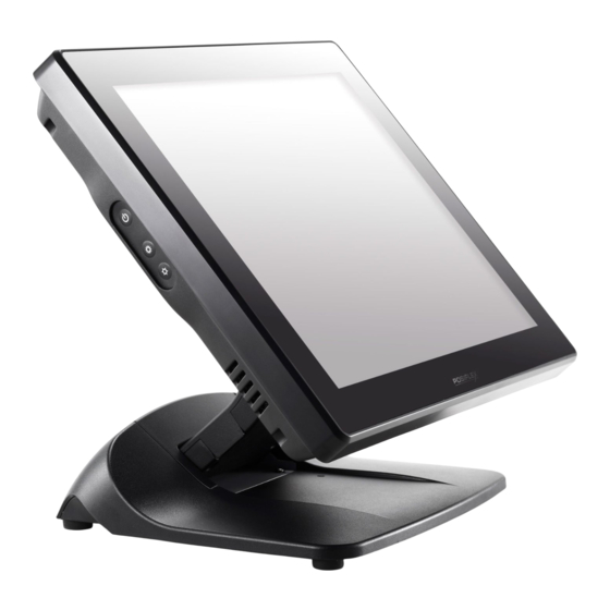
XT-3817
Fanless Touch Terminal
User Manual
Product Features
Intel Bay Trail-D J1900 2.0G CPU, Quad Core, 2MB Cache
DDR3L SO-DIMM slot x 1, max 8GB
True Flat P-Cap touch with 10 points multi-touch
Support Windows 7, POSReady 7, Win 8.1 Industry, Linux per request
Gen 7E or optional Gen 8E foldable base (U.S. Patent #9004436)
16780903020 Ver. A0
http://www.posiflex.com
Package Contents
17" fanless touch terminal with
Gen 7E or Gen 8E base stand (x 1)
Power adapter (x 1)
Power cord (x 1)
User manual (x 1)
Recovery DVD or Information
DVD (x 1)
1
Advertisement

Related Manuals for POSIFLEX XT-6315


Summary of Contents for POSIFLEX XT-6315
- Page 1 DDR3L SO-DIMM slot x 1, max 8GB True Flat P-Cap touch with 10 points multi-touch Support Windows 7, POSReady 7, Win 8.1 Industry, Linux per request Gen 7E or optional Gen 8E foldable base (U.S. Patent #9004436) 16780903020 Ver. A0 http://www.posiflex.com...
- Page 2 Views of the XT-3817 with Gen 7E Base Stand Front View XT-3817 P-Cap Touch Panel LED indicator Gen 7E Base Stand I/O Compartment Rear View Cover HDD Cover Cable Arrangement Cover Neck Cover Cable Cover Cable Exit Side View Power Button Brightness Adjustment Button +...
- Page 3 Bottom View Rubber Feet with Fixing Screw Cable Exit Cable Holder Rubber Feet with Fixing Screw Views of the XT-3817 with Gen 8E Base Stand Front View XT-3817 P-Cap Touch Panel Gen 8E Base Stand LED indicator Rear View I/O Compartment Cover HDD Cover Cable Arrangement...
- Page 4 Side View Power Button Brightness Adjustment Button + Brightness Adjustment Button - Bottom View Rubber Feet with Fixing Screw Power Adapter Compartment UPS Battery Compartment PoweredUSB Compartment Rubber Feet with Fixing Screw View of I/O Interface of XT-3817 DC IN Power Connector USB Ports...
- Page 5 Positioning your POS for a Perfect Viewing Angle The adjustable base stands designed for XT-3817 come in two models, Gen 7E/8E, and allow you to determine an ideal position for your terminal using its unique tilt adjustment mechanism. As the below figures suggest, both Gen 7E and Gen 8E base stands provide three standard positioning solutions for your terminal: flat folded mode, low profile mode, and full extended mode.
- Page 6 XT-3817 with Gen 7E Base Stand Unpack XT-3817, which is supposed to be set in flat folded mode, out of the package box and then lay your POS system on a flat surface. Steady the base stand with one hand, and then tilt the screen downwards.
- Page 7 Restore your terminal to Flat Folded mode from Full Extended mode. Tilt your screen in a horizontal position. Remove the cable cover from the base stand. Support the screen with one hand holding onto its bottom edge. While pulling the lever backwards, move the display downwards until the lever is lifted off the hook as shown in the figure Hook Lever...
- Page 8 Position the terminal in Low Profile mode. Follow Step 4 to set up the termimal in Flat Folded mode. With on hand holding the base, tilt the screen all the way down To tilt screen up or down to your desired angle, please be advised to keep the base stand steady with one hand to do so.
- Page 9 Push the cable cover outwards to remove it from the base stand. Position your terminal in Full Extended mode. Support the screen with one hand holding onto its bottom edge. Then, while pulling the lever backwards, move the display upwards until the lever is snapped into the lower hook to raise the screen as shown in the below figure.
- Page 10 Position the terminal in Low Profile mode. Properly tilt the screen up or down to make sure the cable cover could be removed easily. Then, release the cable cover from the base. Support the screen with one hand holding onto its bottom edge. Then, while pulling the lever backwards, move the display upwards or downwards until the lever is snapped into the upper hook to lower the screen as shown in the below figure.
- Page 11 Return the terminal back to Flat Folded mode. While steadying your terminal with your hand holding onto the base stand, tilt your screen up. Then, make sure the cable cover is removed from the base stand. Support the screen with one hand holding onto its bottom edge. While pulling the lever backwards, release the lever back to the point above the upper hook as shown in the figure.
- Page 12 Routing and Arranging Cables Gen 7E/8E fordable bases feature the specially-designed cable management to help you well organize the cords whenever you need to connect peripheral devices to XT-3817. The following provides some useful cable-routing instructions required to manage your cables. XT-3817 with Gen 7E base will be used to demonstrate the basic routing rules for your reference.
- Page 13 Tilt the terminal up enough to have the bottom I/O plate towards you. Remove the cable arrangement cover by pushing it up in the direction shown by the arrow. Cable Arrangement Cover Properly insert the cable into the correct port on the bottom I/O plate.
- Page 14 Make sure the cable could be pulled out of the cable exit from the bottom of the base. Gen 7E base Gen 8E base Installing Optional Upgrade Kits and Peripherals XT-3817 is an expandable model which allows you to upgrade its own capacity by additionally installing multiple peripheral devices, such as magnetic stripe reader (MSR), LCD monitor and cash drawer, according to your preference.
- Page 15 Please go through the below steps to install the power adapter into Gen 8E base stand. If the power adapter is already installed to Gen 8E base stand, you may skip this section Lay your POS terminal on a flat surface with its bottom facing towards you.
- Page 16 Properly secure the bracket for power adapter. For 150W power adapter, after pushing the power adapter up to the top, place two brackets separately on the top and bottom sides of the power adapter compartment as shown in the figure, and then fasten them with four fixing screws.
- Page 17 Pass the cable of the power adapter Cable Exit through the cable exit and then connect it to the port on the I/O plate of your POS system. (Please refer to Routing and Arranging Cables section to thread the cable, according to the model of your base stand.) Neatly thread the cord along the bottom edge of the PoweredUSB compartment (1), and then use the cable tie to hold the extra cable...
- Page 18 To hold the power cord into place, attach the screw hole of power cord holder to the hole at the bottom of Gen 8E base stand, and then use a fixing screw to secure the bracket. Power Cord Holder Installing Side Mount Upgrade Kits Located at left side on the back of your LCD panel, side mount compartment is...
-
Page 19: Operation Environment
Performing System Recovery For XT-3817 model with preloaded operating systems, Recovery DVD which includes useful utilities will be provided in the package to assist you in efficiently restoring or repairing your damaged system. However, you are not encouraged to recover your system without the help of system integrators. Please be advised to contact your service center for further assistance with system recovery. - Page 20 PU-490:24V x 1 + 12V x 3 via Gen 8E base LAN Port 10 / 100 / 1000 Mb x 2 VGA Port VGA x 1, D-SUB 15 pin with 12V support for Posiflex monitors CR Port 1, 2 CR control UPS Port Yes, optional 2300mAh / 12V Battery...
Need help?
Do you have a question about the XT-6315 and is the answer not in the manual?
Questions and answers