Advertisement
Quick Links
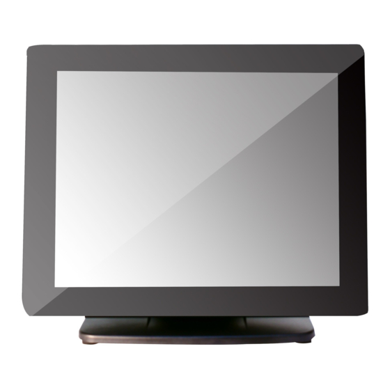
XT-3815-G2/3915-G2/3915IR-G2
Fanless LCD Touch Terminal
User Manual
Product Features
Standard Features
System
Intel Elkhart Lake J6412 2.00G up to 2.60G, 4 cores; Intel
Elkhart Lake N6210 1.20G up to 2.60G, 2 cores
Mechanical Structure
Fanless structure with Aluminum die-cast main unit casing
Water resistant structure allowing easy cleaning
Foldable base
Display
High-quality 15" TFT active matrix LCD monitor provided
with true-flat Projected Capacitive touch panel supporting
10-point multi-touch for XT-3815-G2, with resistive touch
panel for XT-3915-G2, and with Infrared touch panel for
XT-3915IR-G2
16780906010 Ver. A0
http://www.posiflex.com
Package Contents
Terminal with base stand.........x1
60W power adaptor...............x1
Power cord..........................x1
Screw for IO cable cover.........x2
User manual........................x1
Recovery or information CD......x1
1
Advertisement

Related Manuals for POSIFLEX XT-3815-G2


Summary of Contents for POSIFLEX XT-3815-G2
- Page 1 Foldable base Display High-quality 15” TFT active matrix LCD monitor provided with true-flat Projected Capacitive touch panel supporting 10-point multi-touch for XT-3815-G2, with resistive touch panel for XT-3915-G2, and with Infrared touch panel for XT-3915IR-G2 16780906010 Ver. A0 http://www.posiflex.com...
- Page 2 SOME IMPORTANT NOTES FCC NOTES This equipment has been tested and found to comply with the limits for a Class A digital device, pursuant to part 15 of the FCC Rules. These limits are designed to provide reasonable protection against harmful interference when the equipment is operated in a commercial environment.
- Page 3 警告使用者 此為甲類資訊技術設備,於居住環境中使用時,可能會造成射頻擾動, 在此種情況下,使用者會被要求採取某些適當的對策。 BATTERY CAUTION NOTES Dispose of used batteries according to the instructions. Replacement of a battery with an incorrect type that can defeat a safeguard (for example, in the case of some lithium battery types) Disposal of a battery into fire or a hot oven, or mechanically crushing or cutting of a battery that can result in an explosion.
- Page 4 Power adapter kits for 60W/80W/150W power adapters Back mount displays, such as LM/TM-3010/3014 and PD- 6307 Views of the XT-3815-G2/3915-G2/3915IR-G2 Front and Rear Views of Terminal with Gen 7E Base Stand LCD Touch Panel Hinge for main unit...
- Page 5 Left Side View of Terminal with Gen 7E Base Stand Power Button Brightness Adjustment Button “+” Brightness Adjustment Button “-” USB 3.0 Port Locking Hook Bottom View of Terminal with GEN 7E Base Stand Bottom Plate Rubber Cushion Wrapping Screw Front and Rear Views of Terminal with GEN 8E Base Stand LCD Touch Panel Hinge...
- Page 6 Left Side View of Terminal with GEN 8E Base Stand Power Button Brightness Adjustment Button “+” Brightness Adjustment Button “-” USB 3.0 Port Locking Hook Bottom View of Terminal with GEN 8E Base Stand UPS Chamber Bottom Plate Power Adaptor Chamber PoweredUSB Board Cover Rubber Cushion Wrapping Screw...
- Page 7 LCD panel while setting up the tilt angle. XT-3815-G2/3915-G2/3915IR-G2 with Gen 7E Base Please refer to the following instructions on how to switch among different positioning modes to find an ideal viewing angle for XT-3815-G2/3915- G2/3915IR-G2 with Gen 7E base. Unpack XT-3815-G2/3915-G2/3915IR-G2,...
- Page 8 Steady the base with one hand, and then tilt the screen downwards. Position your terminal in Full Extended mode After grabbing the bottom edge of the screen with your hand, gently move the screen upward until the screen is locked into place with a click sound.
- Page 9 With the screen facing toward you, tilt the screen up or down to your desired angle. Please do not press on the LCD panel while setting up the tilt angle. Remove the cable cover from the base. Fix the base with two #/6/32-14L screws. Return your terminal back to Flat Folded mode from Full Extended mode.
- Page 10 4.2 Remove the two screws from the base. Remove the two screws. 4.3 Tilt your screen in a horizontal position. 4.4 Support the screen with one hand holding onto its bottom edge. While pulling the lever backwards, move the display downwards until the lever is lifted off the hook as shown in the figure.
- Page 11 LCD panel while setting up the tilt angle. XT-3815-G2/3915-G2/3915IR-G2 with Gen 8E Base Please refer to the following instructions on how to switch among different positioning modes to find an ideal viewing angle for XT-3815-G2/3915- G2/3915IR-G2 with Gen 8E base.
- Page 12 Unpack XT-3815-G2/3915-G2/3915IR- G2, which is supposed to be set in flat folded mode, out of the package box and then lay your POS system on a flat surface. While steadying the terminal with your hand holding onto the base, tilt the screen down.
- Page 13 Fix the base with two #6/32-14L screws. Push the cable cover back. Position the terminal in Low Profile mode. While keeping your terminal steady with your hand holding on to the base, tilt your terminal down. Then, remove the cable cover from the base.
- Page 14 Remove the two screws from the base. Remove the two screws. Support the screen with one hand holding onto its bottom edge. Then, while pulling the lever backwards, move the display upwards or downwards until the lever is snapped into the upper hook to lower the screen as shown in the below figure.
- Page 15 Return the terminal back to Flat Folded mode. While steadying your terminal with your hand holding onto the base, tilt your screen up. Support the screen with one hand holding onto its bottom edge. While pulling the lever backwards, release the lever back to the point above the upper hook as shown in the figure.
- Page 16 The introduction to the kit and the brief description of installation of the kit are made below. For the detailed description of installation of the 80W/150W power adapter kit, refer to the XT-3815-G2/3915-G2/3915IR-G2 technical manual. Secure the Power Cord...
-
Page 17: Power Indicator
Le cordon d'alimentation doit être connecté à une prise de courant avec mise à la terre. Powering ON the XT-3815-G2/3915-G2/3915IR-G2 After connecting the power cable to the power jack of main unit, slightly push to open the power button cover at the left side of the main unit. -
Page 18: Installing An Operating System
This product is highly professional equipment. Therefore, we do NOT encourage you to install any operating system into this machine. Posiflex Technology, Inc. shall not be responsible for any technical support to questions on this aspect. We suggest that you contact your dealer for OS installation. - Page 19 Humidity: 10 to 90 %; 5 to 90 % (operation condition) ※ The product information and specification are subject to change without prior notice. To get the detailed information on XT-3815-G2/3915-G2/3915IR-G2, please check this model from Posiflex Global Website (http://www.posiflex.com/en-global/Download/download).
- Page 20 <MEMO>...
Need help?
Do you have a question about the XT-3815-G2 and is the answer not in the manual?
Questions and answers