Advertisement
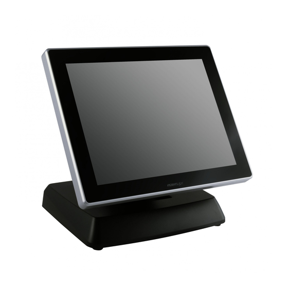
XT-3615/3815
Fanfree LCD Touch Terminal
User's Manual
Rev.: Original
FCC Notes:
This equipment generates, uses, and can radiate radio frequency energy and, if not
installed and used in accordance with the instructions manual, may cause interference
to radio communications. It has been tested and found to comply with limits for a Class
A digital device pursuant to subpart J of Part 15 of FCC Rules, which are designed to
provide reasonable protection against interference when being operated in a commercial
environment. Operation of this equipment in a residential area is likely to cause
interference in which case the user at his or her own expense will be required to take
whatever measures to correct the interference.
Warranty Limits:
Warranty terminates automatically when any person other than the authorized
technicians opens the machine. The user should consult his/her dealer for the problem
having happened. Warranty voids if the user does not follow the instructions in
application of this merchandise. The manufacturer is by no means responsible for any
damage or hazard caused by improper application.
About This Manual:
Posiflex has made every effort for the accuracy of the content in this manual. However,
Posiflex Technology, Inc. will assume neither liability for any technical inaccuracies or
editorial or other errors or omissions contained herein, nor that for direct, indirect,
incidental, consequential or otherwise damages, including without limitation loss of
data or profits, resulting from the furnishing, performance, or use of this material.
This information is provided "as is" and Posiflex Technology, Inc. expressly disclaims
any warranties, expressed, implied or statutory, including without limitation implied
warranties of merchantability or fitness for particular purpose, good title and against
infringement.
The information in this manual contains only essential hardware concerns for general
user and is subject to change without notice. Posiflex Technology, Inc. reserves the
right to alter product designs, layouts or drivers without notification. The system
integrator shall provide applicative notices and arrangement for special options utilizing
this product. The user may find the up-to-date information of the hardware from:
http://www.posiflex.com or http://www.posiflex.com.tw or http://www.posiflexusa.com.
A backup of all data should be kept prior to installation of a drive unit or storage
peripheral. Posiflex will not be responsible for any loss of data resulting from the use,
disuse or misuse of this or any other Posiflex product.
P/N: 16780900010
1
Advertisement
Table of Contents

Related Manuals for POSIFLEX XT-3615


Summary of Contents for POSIFLEX XT-3615
- Page 1 About This Manual: Posiflex has made every effort for the accuracy of the content in this manual. However, Posiflex Technology, Inc. will assume neither liability for any technical inaccuracies or editorial or other errors or omissions contained herein, nor that for direct, indirect, incidental, consequential or otherwise damages, including without limitation loss of data or profits, resulting from the furnishing, performance, or use of this material.
- Page 2 Posiflex Technology, Inc., the publisher of this documentation. © Copyright Posiflex Technology, Inc. 2014 All brand and product names and trademarks are the property of their respective holders.
- Page 3 XT series also offers ample of performance and flexibility to satisfy the most demanding of daily POS operations. The XT-3615/3815 series comes with the selection of two newly designed foldable bases, the curvy slim Generation 7E Base and the larger but practical Generation 8E Base.
- Page 4 Support high-performance DDR3L 1333 FSB, SO-DIMM socket *1, 4GB (Max.) for XT-3615 (N2807) and 8GB (Max.) for XT-3815 (J1900) VGA memory support DVMT 4.0 Mechanical Structure Fanfree structure with Aluminum die-cast main unit casing An advanced GEN 8E base design that supports storage...
- Page 5 System DDR3L SODIMM memory expansions up to 4GB (Max.) for XT-3615 (N2807) and 8GB (Max.) for XT-3815 (J1900) in one SODIMM Preload Windows POSReady 7 / Win 7 / Windows Embedded 8.1 Industry / Linux per request WIFI ...
- Page 6 Power cord x 1 User manual & CD x 1 Wall mount kit (optional) x1 Views of XT-3615/3815 Front and Rear Views of XT-3615/3815 with Gen 7E Base Stand HDD Cover LCD Touch Panel Hinge for LCD Power Indicator...
- Page 7 Bottom View of XT-3615/3815 with GEN 7E Base Stand Bottom Plate HDD Cover Rubber Cushion Wrapping Screw Front and Rear Views of XT-3615/3815 with GEN 8E Base Stand HDD Cover LCD Touch Panel Hinge for LCD Cable Cover Cable Exit...
-
Page 8: Operation Environment
Bottom View of XT-3615/3815 with GEN 8E Base Stand UPS Chamber Bottom Plate Power Adaptor Chamber Powered USB Board Cover Rubber Cushion Wrapping Screw Views of I/O Interfaces 1 DC-IN Power Jack 6 VGA Port 2 UPS Port 7 LAN Port 3 CR Port 8 USB 2.0 Port... - Page 9 Installing Optional Upgrade Kits Upon your demands, you can install optional upgrade kits respectively onto XT-3615/3815 main unit and GEN 7E/8 base stand. The introduction to the kits and the brief description of installation of the kits are made below.
- Page 10 For the detailed description of installation of the rear top mount upgrade kit, refer to the XT-3615/3815 technical manual or the user manual of LM/TM-series peripheral kit. Note: When being installed with the LM/TM- 3014/3015-XT, the XT system must be provided with a 80W power adapter.
- Page 11 If you install both the hard disk drive kit and the UPS battery kit, firstly install the hard disk drive kit and then the UPS battery kit. For the detailed description of installation of the UPS battery kit, refer to the XT-3615/3815 technical manual or the user manual of UPS battery kit.
- Page 12 For the detailed description of installation of the 80W power adapter kit, refer to the XT-3615/3815 technical manual or the user manual of GEN 8E base stand. 2. For 120W/150W Power Adapter...
-
Page 13: Connecting Cables
For the detailed description of installation of the powered USB adapter kit, refer to the XT-3615/3815 technical manual or the user manual of GEN 8E base stand. Note: When the powered USB adapter kit is installed, the XT system must be provided with a 150W power adapter. - Page 14 Routing and Arranging Cables For GEN 7E Base Stand Before connecting cables, please follow the steps made below to remove the cable cover from the GEN 7E base stand for routing and arranging the cables. 1. Press section A with your thumb and push against section B with your forefinger.
- Page 15 5. The cable cover and the neck cover are well removed, as shown in the right figure. 6. Then, slide the cable arrangement cover to remove from the base stand. After removing the covers illustrated above, follow steps made below to route the cables from the bottom of base stand to the I/O interfaces of the main unit.
- Page 16 Powering ON/OFF the XT-3615/3815 After connecting the power cable to the power jack of main unit, slightly push to open the power button cover at the left side of the main unit. Then press the power button to power on the main unit.
-
Page 17: Installing An Operating System
PC veterans. Therefore, we do NOT encourage you to install any operating system into this machine. Posiflex Technology, Inc. shall not be responsible for any technical support to questions on this aspect. -
Page 18: Operating System Recovery
Then follow instructions from your system integrator for software recovery. This recovery DVD is provided for the XT-3615/3815 only. Do NOT use a recovery DVD for another model of machine to recover the operating system of your XT-3615/3815; otherwise,... -
Page 19: Touch Panel
Touch Panel The XT-3615/3815 is provided with a projected capacitive touch panel. The description described below is applicable for models provided with a touch panel only. The user of those models without any touch panel can ignore them. -
Page 20: Specifications
Specifications XT-3615 XT-3815 Intel Bay Trail-M N2807 1.58G up to Intel Bay Trail-D J1900 2.0G up to 2.16G, 1M Cache, Dual core 2.42G, 2M Cache, 4 core DDR3L 1333 FSB, SO-DIMM DDR3L 1333 FSB, SO-DIMM Memory socket *1, 4G socket *1, 8G POSReady 7 / Win 7 / Windows Embedded 8.1 Industry / Linux per request...
Need help?
Do you have a question about the XT-3615 and is the answer not in the manual?
Questions and answers