Advertisement
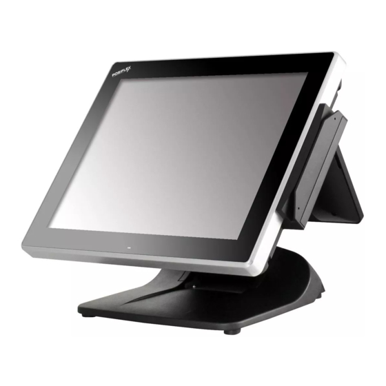
XT– 3015/3017/3215/3215I
Fanfree LCD Touch Terminal
User's Manual
Rev.: C0
FCC Notes:
This equipment generates, uses, and can radiate radio frequency energy and, if not installed and
used in accordance with the instruction manual, may cause interference to radio communications.
It has been tested and found to comply with limits for a Class A digital device pursuant to subpart
B of Part 15 of FCC Rules, which are designed to provide reasonable protection against
interference when operated in a commercial environment. Operation of this equipment in a
residential area is likely to cause interference in which case the user at his owns expense will be
required to take whatever measures to correct the interference.
Warranty Limits:
Warranty terminates automatically when any person other than the authorized technicians opens
the machine. The user should consult his/her dealer for the problem happening. Warranty voids if
the user does not follow the instructions in application of this merchandise. The manufacturer is by
no means responsible for any damage or hazard caused by improper application.
About This Manual:
Posiflex has made every effort for the accuracy of the content in this manual. However, Posiflex
Technology, Inc. will assume no liability for any technical inaccuracies or editorial or other errors
or omissions contained herein, nor for direct, indirect, incidental, consequential or otherwise
damages, including without limitation loss of data or profits, resulting from the furnishing,
performance, or use of this material. This information is provided "as is" and Posiflex Technology,
Inc. expressly disclaims any warranties, expressed, implied or statutory, including without
limitation implied warranties of merchantability or fitness for particular purpose, good title and
against infringement. The information in this manual contains only essential hardware concerns
for general user and is subject to change without notice. Posiflex Technology, Inc. reserves the
right to alter product designs, layouts or drivers without notification. The system integrator shall
provide applicative notices and arrangement for special options utilizing this product. The user
may find the most up to date information of the hardware from: http://www.posiflex.com or
http://www.posiflex.com.tw or http://www.posiflexusa.com . All data should be backed-up prior to
the installation of any drive unit or storage peripheral. Posiflex will not be responsible for any loss
of data resulting from the use, disuse or misuse of this or any other Posiflex product. All rights are
strictly reserved. No part of this documentation may be reproduced, stored in a retrieval system, or
transmitted in any form or by any means, electronic, mechanical, photocopying, or otherwise,
without prior expressly written consent from Posiflex Technology, Inc. the publisher of this
documentation.
© Copyright Posiflex Technology, Inc. 2016
All brand and product names and trademarks are the property of their respective holders.
P/N: 16640900040
Advertisement
Table of Contents

Subscribe to Our Youtube Channel
Related Manuals for POSIFLEX XT–3015


Summary of Contents for POSIFLEX XT–3015
- Page 1 Posiflex will not be responsible for any loss of data resulting from the use, disuse or misuse of this or any other Posiflex product. All rights are strictly reserved. No part of this documentation may be reproduced, stored in a retrieval system, or transmitted in any form or by any means, electronic, mechanical, photocopying, or otherwise, without prior expressly written consent from Posiflex Technology, Inc.
- Page 2 ALERT TO OUR HONORABLE CUSTOMERS: Please always read thoroughly all the instructions and documents delivered with the product before you do anything about it. Don’t take any premature action before you have a full understanding of the consequences. This product contains inside a Lithium battery. Please always follow local environmental protection laws / regulations for disposal of used batteries and always replace only with battery of same type.
- Page 3 INTRODUCTION PRODUCT PICTURES FOR Gen 7/E&8/E BASE STAND Gen 7 Base Front View Rear View Gen 8 Base Front View Rear View Side View for XT-3015/3215/3215I Switch Buttons Part 3...
- Page 4 Side View for XT-3017 Switch Buttons Base Stand and Bottom View Gen 7 Base Gen 8 Base Part 4...
-
Page 5: Parts Identification
Gen 7E Base Gen 8E Base PARTS IDENTIFICATION Main Unit LCD touch panel Power indicator Gen 7 ,8 base stand Hinge for LCD terminal HDD cover Power switch Brightness adjust push button “+” Brightness adjust push button “-” 10. USB port 11. - Page 6 I/O Plate View for XT-3015/3215/3215I A) COM1 (DB9) port B) COM2 (DB9) port C) COM3 (DB9) port D) COM4 (RJ50) port E) USB0~3 port F) LAN1~2 port G) VGA port H) CR port +12V UPS BAT port 1 x DC IN power connector I/O Plate View for XT-3017 A) CR port B) LAN1~2 port...
-
Page 7: Product Features
image. Each curve and detail of the POS terminal should add something to the overall mood of the store, to lift the shopping experience of the customers. With a bezel free/bezel type touch screen, beautifully sculptured slim body, sexily curved base stand, XT-3015/3017/3215/3215I series looks right at home at any elegantly decorated store. - Page 8 LCD brightness adjust buttons at side of main unit. Durable resistive type touch panel, P-Cap, IR. Dual display support (per OS capability). VGA memory support DVMT 4.0. I/O Interface 4 serial ports with 3 of DB9 connectors and one of 10 pin RJ50 type modular connector with XT-3015/3215/3215I, 4 serial ports with 4 of DB9 connectors with XT-3017.
- Page 9 DDR3 SODIMM memory expansions up to 4GB max in one SO- DIMM. Integrated side mount upgrade kit: SA-105Z: with optional MSR; Wi-Fi SA-205Z: iButton SA-305Z: 3 track MSR, RFID and Finger Print Sensor SA-405Z: 3G, MSR and Finger Print Sensor Preload POSReady7 /POSReady2009/ Win 7 / Windows Embedded 8.1 Industry/ Linux by request.
- Page 10 Step B: Release the compression lock of base stand cover at both sides to remove the base stand cover. Step C: Route through the indicated passage from Gen 7/8 base. Securing the AC Power Cord for Gen 8/8E base To avoid the AC power cord from being pulled out accidentally, the 80W/150W power adapter kits are shipped with a power cord bracket.
- Page 11 Fixing with screw REAR MOUNT UPGRADE KIT Please follow the instructions on the manual that comes along with the customer display LM/TM-3010F/3014F/3015F/LM-6607, PD-6607U/PD- 350UE/PD-2608UE if installed. There are LM/TM-3010F/3014F/3015F/LM-6607 available for 2nd LCD display, needed to combine with XT-3015/3017/3215/3215I with supporting bracket to tighten.
- Page 12 Step D: If 2 TM display is ready for installation, release either cable cover for VGA cabling by unfastening the 2 screws on the cable cover, route one VGA cable thru cable cover. Then connect one end of the cable to the LM VGA port, connect the other end of the cable to the system VGA port.
- Page 13 Step C: Push the lower right/left stopper (long) upward with your thumb to remove, and then push the upper right/left stopper (short) to the right/left with your thumb to remove. Step D: Draw the VGA (USB) cable through the cavity between the rear side of terminal and the viewing-angle adjustment plate of base stand.
-
Page 14: Operating System Installation
OPERATING SYSTEM INSTALLATION OS installation into a system without preloaded OS is highly discouraged. Posiflex Technology, Inc. shall not be responsible for any technical support to questions on this aspect. APPLICATION ENVIRONMENT It is very important that you check the following operational guidelines:... -
Page 15: Power On/Off
ventilation. There must be at least 25 mm air clearance around any top or side ventilation holes with a free flow of air around the unit at ALL times for the installation. Operating Environment The equipment must not be operated or stored in extremes of both temperature and humidity/moisture. - Page 16 System External Indicator Status UPS Battery Powering Up Status Power Not present Not possible Present Not allowed Orange No influence Allowed Blue No influence Not required Blue/flash Activated Not required Orange/rapid Running at Not required flash low capacity Hardware Power Switch The power switch located in the left side of the main unit is a push on/off switch.
-
Page 17: Brightness Control
The VGA port in the XT-3015/3017/3215/3215I system supports either a separately connected LCD monitor or touch monitor. To support the DC power to the Posiflex LCD display, have a qualified technician to set the power supply in XT main unit through the VGA connector according to Posiflex technical information. -
Page 18: Parallel Port
before the power in this port is disabled. SERIAL PORTS – COM1/2/3/4 In XT-3015/3215/3215I system, there are 3 serial ports in form of DB 9 pin male connectors and 1 in form of 10 pin RJ50 type modular connector available. In XT-3017 system, there are 4 serial ports in form of DB9 pin male connectors available.
Need help?
Do you have a question about the XT–3015 and is the answer not in the manual?
Questions and answers