Advertisement
Quick Links
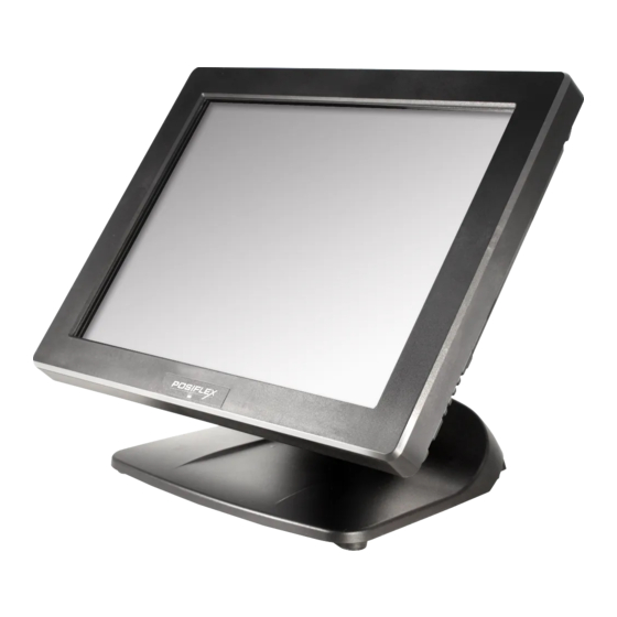
XT-3815/3915/3915IR
Fanless LCD Touch Terminal
User Manual
Product Features
Standard Features
System
Intel Bay Trail-D J1900 2.0G up to 2.42G, 2M Cache, 4 core
Mechanical Structure
Fanless structure with Aluminum die-cast main unit casing
Water resistant structure allowing easy cleaning
Foldable base
Display
High-quality 15" TFT active matrix LCD monitor provided
with true-flat Projected Capacitive touch panel supporting
10-point multi-touch for 3815, with resistive touch panel for
XT-3915, and with Infrared touch panel for XT-3915IR
16780900050 Ver. D0
http://www.posiflex.com
Package Contents
Terminal with base stand.........x1
60W power adaptor...............x1
Power cord..........................x1
Screw for IO cable cover.........x2
User manual........................x1
Recovery or information CD......x1
1
Advertisement

Related Manuals for POSIFLEX XT-3915


Summary of Contents for POSIFLEX XT-3915
- Page 1 Foldable base Display High-quality 15” TFT active matrix LCD monitor provided with true-flat Projected Capacitive touch panel supporting 10-point multi-touch for 3815, with resistive touch panel for XT-3915, and with Infrared touch panel for XT-3915IR 16780900050 Ver. D0 http://www.posiflex.com...
- Page 2 Optional Items System DDR3L SODIMM memory expansions up to 8GB (Max.) for XT-3815/3915/3915IR (J1900) in one SODIMM Preload Windows POSReady 7 / Win 7 / Windows Embedded 8.1 Industry / Linux per request WIFI Wireless LAN module, through Mini PCI-E Interface Connection Cable ...
- Page 3 Views of the XT-3815/3915/3915IR Front and Rear Views of Terminal with Gen 7E Base Stand HDD Cover LCD Touch Panel Hinge for main unit Power Indicator Neck Cover Cable Cover Base Stand Cable Exit DDR3 Memory Cover Left Side View of Terminal with Gen 7E Base Stand Power Button Brightness Adjustment Button “+”...
- Page 4 Front and Rear Views of Terminal with GEN 8E Base Stand HDD Cover LCD Touch Panel Hinge for main unit Cable Cover Cable Exit Neck Cover Power Indicator Base Stand DDR3 Memory Cover Left Side View of Terminal with GEN 8E Base Stand Power Button Brightness Adjustment Button “+”...
- Page 5 Views of I/O Interfaces of Terminal 1 DC-IN Power Jack 6 VGA Port 2 UPS Port 7 LAN Port 3 CR Port 8 USB 2.0 Port 4 DB9 COM Port 9 USB 2.0 Port 5 RJ50 COM Port 10 USB 3.0 Port Positioning your POS for a Perfect Viewing Angle The adjustable bases designed for XT-3815/3915/3915IR come in two models, Gen 7E/8E, and allow you to determine an ideal position for your terminal by...
- Page 6 In general, XT-3815/3915/3915IR will be set up beforehand in Flat Folded mode and then packaged into the box for shipping. After it is unpacked, you may re-adjust the terminal in either Low Profile mode or Full Extended mode according to your situation. Below will provide instructions on how to adjust the specific base connected to the POS system.
- Page 7 Support the screen with one hand holding onto its bottom edge. Then, while pulling the lever backwards, move the display upwards until the lever is snapped into the lower hook to raise the screen as shown in the below figure. Lower hook Lever...
- Page 8 Fix the base with two #/6/32-14L screws. Return your terminal back to Flat Folded mode from Full Extended mode. Remove the cable cover from the base. 4.2 Remove the two screws from the base. Remove the two screws.
- Page 9 4.3 Tilt your screen in a horizontal position. 4.4 Support the screen with one hand holding onto its bottom edge. While pulling the lever backwards, move the display downwards until the lever is lifted off the hook as shown in the figure. Hook Lever 4.5 Push the cable cover back.
- Page 10 Position the terminal in Low Profile mode. Follow Step 4 to set up the termimal in Flat Folded mode. Tilt the screen all the way down To tilt screen up or down to your desired angle, please be advised to keep the base steady with one hand to do so.
- Page 11 Push the cable cover outwards to remove it from the base. Position your terminal in Full Extended mode. Support the screen with one hand holding onto its bottom edge. Then, while pulling the lever backwards, move the display upwards until the lever is snapped into the lower hook to raise the screen as shown in the below figure.
- Page 12 Fix the base with two #/6/32-14L screws. Push the cable cover back. Position the terminal in Low Profile mode. While keeping your terminal steady with your hand holding on to the base, tilt your terminal down. Then, remove the cable cover from the base.
- Page 13 Remove the two screws from the base. Remove the two screws. Support the screen with one hand holding onto its bottom edge. Then, while pulling the lever backwards, move the display upwards or downwards until the lever is snapped into the upper hook to lower the screen as shown in the below figure.
- Page 14 Return the terminal back to Flat Folded mode. While steadying your terminal with your hand holding onto the base, tilt your screen up. Support the screen with one hand holding onto its bottom edge. While pulling the lever backwards, release the lever back to the point above the upper hook as shown in the figure.
- Page 15 Installing Power Adapter Kit onto GEN 8E Base Stand The power adapter kit is optional and, before shipping, is installed onto the optional GEN 8E base stand. Upon your needs, you can purchase and install the kit for 80W or 150W power adapter.
-
Page 16: Power Indicator
This product is highly professional equipment. Therefore, we do NOT encourage you to install any operating system into this machine. Posiflex Technology, Inc. shall not be responsible for any technical support to questions on this aspect. We suggest that you... -
Page 17: Specifications
Humidity: 10 to 90 %; 5 to 90 % (operation condition) ※ The product information and specification are subject to change without prior notice. To get the detailed information on XT-3815/3915/3915IR, please check this model from Posiflex Global Website (http://www.posiflex.com/en-global/Download/download). - Page 18 <MEMO>...
- Page 19 <MEMO>...
- Page 20 <MEMO>...
Need help?
Do you have a question about the XT-3915 and is the answer not in the manual?
Questions and answers