Advertisement
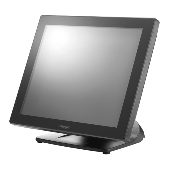
XT-8317/8317E
Fanless POS Terminal
User Manual
Package Contents
17" P-CAP touch terminal with Gen 7E or Gen 8E base.................(x1)
Power adapter....................................................................(x1)
Power cord......................................................................(x1)
FCC NOTES
This system meets industry & government requirements and applicable standards. This
equipment generates, uses, and can radiate radio frequency energy and, if not installed and
used in accordance with the instructions manual, may cause interference to radio
communications. It has been tested and found to comply with limits for a Class A digital
device pursuant to subpart B of Part 15 of FCC Rules, which are designed to provide
reasonable protection against interference when operated in a commercial environment.
Operation of this equipment in a residential area is likely to cause interference in which case
the user at his own expense will be required to take whatever measures to correct the
interference.
This device complies with part 15 of the FCC Rules. Operation is subject to the following
two conditions: (1) This device may not cause harmful interference, and (2) this device must
accept any interference received, including interference that may cause undesired operation.
CE CLASS A WARNING
This equipment is compliant with Class A of CISPR 32. In a residential environment this
equipment may cause radio interference.
AVERTISSEMENT CE CLASSE A
Cet équipement est conforme à la classe A de CISPR 32. Dans un environnement résidentiel,
cet équipement peut provoquer des interférences radio.
WARRANTY LIMITS
Warranty will terminate automatically when the machine is opened by any person other than
the authorized technicians. The user should consult his/her dealer for the problem happening.
Warranty voids if the user does not follow the instructions in application of this merchandise.
The manufacturer is by no means responsible for any damage or hazard caused by improper
application.
LIMITES DE GARANTIE
La garantie prend fin automatiquement lorsque la machine est ouverte par une personne autre
que les techniciens autorisés. L'utilisateur doit consulter son revendeur pour le problème qui
se produit. La garantie s'annule si l'utilisateur ne suit pas les instructions d'application de
cette marchandise. Le fabricant n'est en aucun cas responsable de tout dommage ou danger
causé par une mauvaise application.
XT-8317/8317E Ver. A0
1
Advertisement
Table of Contents

Related Manuals for POSIFLEX XT-8317


Summary of Contents for POSIFLEX XT-8317
- Page 1 L'utilisateur doit consulter son revendeur pour le problème qui se produit. La garantie s'annule si l'utilisateur ne suit pas les instructions d'application de cette marchandise. Le fabricant n'est en aucun cas responsable de tout dommage ou danger causé par une mauvaise application. XT-8317/8317E Ver. A0...
-
Page 2: Safety Instructions
Risque d'explosion si la batterie est remplacée par un type incorrect. Jetez la batterie usagée conformément aux réglementations locales en matière d'élimination. 警告 本電池如果更換不正確會有爆炸的危險,請依製造商說明書處理用過之電池。 Views of XT-8317/8317E with Gen 7E Base Front View P-CAP Touch Panel Gen 7E Base LED indicator... - Page 3 Rear View Neck Cover Cable Cover Cable Exit Side View Power Button Brightness Adjustment Button + Brightness Adjustment Button - Bottom View Rubber Feet with Fixing Screw Cable Exit Cable Holder Rubber Feet with Fixing Screw...
- Page 4 Views of XT-8317/8317E with Gen 8E Base Front View P-CAP Touch Panel Gen 8E Base LED indicator Rear View Neck Cover Cable Cover Cable Exit Side View Power Button Brightness Adjustment Button + Brightness Adjustment Button -...
- Page 5 Power Connector Positioning your POS for a Perfect Viewing Angle The adjustable bases designed for XT-8317/8317E come in two models, Gen 7E/8E, and allow you to determine an ideal position for your terminal by using its unique tilt adjustment mechanism. As the below figures suggest, both bases provide three standard positioning solutions for your terminal: Flat Folded mode, Low Profile mode, and Full Extended mode.
- Page 6 Low Profile mode Full Extended mode In general, XT-8317/8317E will be set up beforehand in Flat Folded mode and then packaged into the box for shipping. After it is unpacked, you may re- adjust the terminal in either Low Profile mode or Full Extended mode according to your situation.
- Page 7 Support the screen with one hand holding onto its bottom edge. Then, while pulling the lever backwards, move the display upwards until the lever is snapped into the lower hook to raise the screen as shown in the below figure. Lower hook Lever...
- Page 8 Return your terminal back to Flat Folded mode from Full Extended mode. Remove the cable cover from the base. Remove the two screws from the base. Remove the two screws. Tilt your screen in a horizontal position. Support the screen with one hand holding onto its bottom edge. While pulling the lever backwards, move the display downwards until the lever is lifted off the hook as shown in the figure.
- Page 9 XT-8317/8317E with Gen 8E Base Please refer to the following instructions on how to switch among different positioning modes to find an ideal viewing angle for XT-8317/8317E with Gen 8E base. Unpack XT-8317/8317E, which is supposed to be set in flat folded mode, out of the package box and then lay your POS system on a flat surface.
- Page 10 Push the cable cover outwards to remove it from the base. Position your terminal in Full Extended mode. Support the screen with one hand holding onto its bottom edge. Then, while pulling the lever backwards, move the display upwards until the lever is snapped into the lower hook to raise the screen as shown in the below figure.
- Page 11 Push the cable cover back. Position the terminal in Low Profile mode. While keeping your terminal steady with your hand holding on to the base, tilt your terminal down. Then, remove the cable cover from the base. Remove the two screws from the base. Remove the two screws.
- Page 12 5.3 Push the cable cover back. 5.4 Tilt the screen up or down to your desired angle. Please do not press on the LCD panel while setting up the tilt angle. Return the terminal back to Flat Folded mode. While steadying your terminal with your hand holding onto the base, tilt your screen up.
- Page 13 Connecting Power Adapter and I/O Cables To have the terminal ready for operation, please connect the connector of power adapter and all of the connectors of required I/O cables respectively to the 12VDC-IN power jack and appropriate I/O ports. Please make sure that each of the cables is fully connected to each of the correct ports.
- Page 14 Pull outwards the locking levers with your forefingers and then remove the neck cover in the direction shown by the arrow. Tilt the screen to the horizontal position. Thread the cables along the cable passage and then through the cable exit. Tilt the terminal up enough to have the bottom I/O plate towards you.
- Page 15 Gen 8E base Installing Optional Upgrade Kits and Peripherals XT-8317/8317E is an expandable model which allows you to upgrade its own capacity by additionally installing multiple peripheral devices, such as magnetic stripe reader (MSR), LCD monitor, and cash drawer, according to your preference.
- Page 16 Installing Power Adapter to Gen 8E Base Power adapter is used to provide power which your terminal needs to be operated normally. Please go through the below steps to install the power adapter into Gen 8E base. If the power adapter is already installed to Gen 8E base, you may skip this section Lay your POS terminal on a flat surface with its bottom facing towards you.
- Page 17 Pass the cable of the power adapter Cable Exit through the cable exit and then connect it to the port on the I/O plate of your POS system. (Please refer to Routing and Arranging Cables section to thread the cable, according to the model of your base.) Neatly thread the cord along the bottom edge of the PoweredUSB compartment (1), and then use the cable tie to hold the extra cable...
-
Page 18: Installing An Operating System
Installing an Operating System You are highly advised not to install an operating system on XT-8317/8317E without professional instructions. Not only might the careless handling during installation cause irreversible damage to your machine, but also the improper installation likely leads to system malfunction or failure. - Page 19 Operation Environment To prevent XT-8317/8317E from overheating, it is suggested to position your terminal in a well-ventilated working environment. In doing so, please be advised to keep the POS terminal at least 25mm away from other devices to ensure the machine is properly cooled down and functioning normally.
-
Page 20: Specifications
0°C - 40°C, 20%RH - 90%RH Condition Storage -20°C - 70°C, 10%RH - 90%RH ※ The product information and specifications are subject to change without prior notice. To get the detailed information on the XT-8317/8317E, please check this model from Posiflex Global Website.
Need help?
Do you have a question about the XT-8317 and is the answer not in the manual?
Questions and answers