
Related Manuals for Atlanta Attachment Company 1331BX


Summary of Contents for Atlanta Attachment Company 1331BX
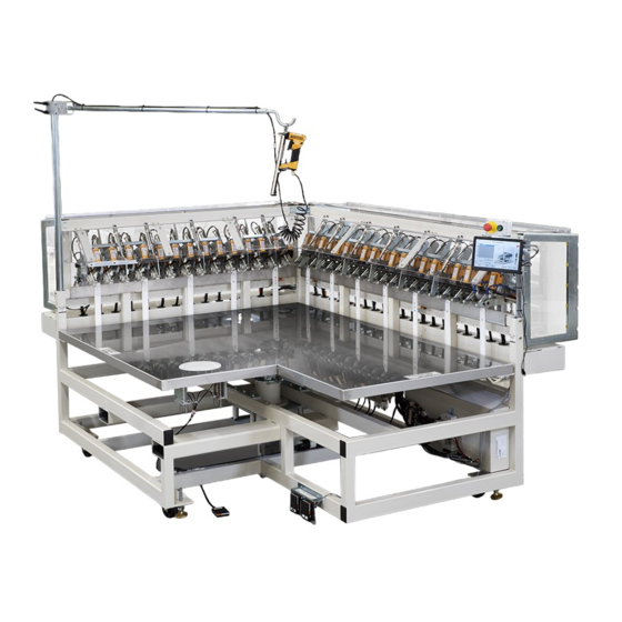
- Page 1 1331BX Model Revision 1 Created Dec 17, 2012 Technical Manual & Parts Lists Atlanta Attachment Company 362 Industrial Park Drive Lawrenceville, GA 30046 770-963-7369 • www.atlatt.com...
- Page 3 Attachment Company. In addition to any confidentiality and non-disclosure obligations that currently exist between you and Atlanta Attachment Company, your use of these materials serves as an acknowledgment of the confidential and proprietary nature of these materials and your duty not to make any unauthorized use or disclosure of these materials.
-
Page 4: Table Of Contents
Technical Manual & Parts Lists Contents Important Safety Instruction ........................1 Liability ..............................2 Safety Equipment on the Machines ......................3 Protective Eyewear ............................. 4 Important Notices............................5 Maintenance ..............................7 Repair ................................8 A Word to the End User..........................9 Safety Precautions ............................ - Page 5 Technical Manual & Parts Lists a. Foundation Edge Stapling Cycle ......................20 b. Dust Cover Stapling Cycle........................21 2.4. Reloading the Staplers........................22 2.5. Basic Preventive Maintenance......................24 a. Daily Maintenance (8 hours): ........................ 24 3. MAINTENANCE MANUAL......................25 3.1.
- Page 6 Technical Manual & Parts Lists 1331042 Pivot Lift Assembly ........................50 1331185 Overhead Staple Gun Holder ..................... 51 1331077 Long Side Staple Gun Assembly ..........Error! Bookmark not defined. 1331078 Short Staple Gun Assembly ....................... 55 1331140 Table Top Assembly ........................57 1331178 Pneumatic Panel .........................
-
Page 7: Important Safety Instruction
Mandatory Information All persons operating and/or working on the 1331BX Foundation Stretcher should read and understand all parts of the Safety Instructions. This applies, in particular, for persons who only operate and/or work on the unit occasionally (e.g. for maintenance and repair). Persons who have difficulty reading must receive particularly thorough instruction. -
Page 8: Liability
Technical Manual & Parts Lists Liability The machine should only be operated when in perfect working order, with due regard for safety and the potential dangers, as well as in accordance with the Instruction Material. Faults and malfunctions capable of impairing safety should be remedied immediately. We cannot accept any liability for personal injury or property damage due to operator errors or non-compliance with the safety instructions contained in this booklet. -
Page 9: Safety Equipment On The Machines
Technical Manual & Parts Lists A Word to the Operator The greatest danger inherent in our machines: is that of fingers, hands or loose clothing being drawn into a machine by live, coasting or rotating tools or assemblies or of being cut by sharp tools or burned by hot elements. LWAYS BE CONSCIOUS OF THESE DANGERS Safety Equipment on the Machines All machines are delivered with safety equipment, which shall not be removed or... -
Page 10: Protective Eyewear
Technical Manual & Parts Lists Protective Eyewear Protective eyewear that has been tested by the local authorities should be worn whenever there is a possibility of loose or flying objects or particles such as when cleaning the machine with compressed air. Tools Always count the number of tools in your possession before starting work on the machine. -
Page 11: Important Notices
Technical Manual & Parts Lists Important Notices Reporting and Fighting Fires Read the instructions posted in the factory with regard to reporting fires and the emergency exits. Make sure you know exactly where the fire extinguishers and sprinkler systems are located and how they are operated. - Page 12 Technical Manual & Parts Lists - Kinetic energy - Note that some motors or spindles, for example, may continue to run or coast run on after being switched off. - Potential energy - Individual assemblies may need to be secured if necessary for repair work. Delivery of the Machine/Packaging Note any markings on the packaging, such as weights, lifting points and special information.
-
Page 13: Maintenance
Technical Manual & Parts Lists Protect against influences from the surroundings: no structure-borne vibrations, no grinding dust, or chemical vapors. Protect against unauthorized access. Ensure that the machine and accessories are set up in a stable position. Ensure easy access for operation and maintenance (Instruction Manual and layout diagram); also verify that the floor is strong enough to carry the weight of the machine. -
Page 14: Repair
Technical Manual & Parts Lists Repair Replacement Parts We cannot accept any liability whatsoever for damage due to the use of parts made by other manufacturers or due to unqualified repair or modification of the machine. Repair, Electrical The power supply must be switched off (master switch off) and secured so that it cannot be switched on again inadvertently before starting any work on live parts. -
Page 15: A Word To The End User
Technical Manual & Parts Lists A Word to the End User The end user has sole responsibility to enforce the use of safety procedures and guards on the machine. Any other safety devices or procedures due to local regulations should be should be retrofitted in accordance to these regulations and/or the EC Directive on the safety of machines. -
Page 16: Installation Manual
Technical Manual & Parts Lists 1. INSTALLATION MANUAL 1.1. Parts Description Emergency Stop Feed Stops Start Button 10 Forklift Channels Touch Screen Panel 11 Leveling Bolts Staplers 12 Stainless Steel Table Tension Wheels 13 Border Clamps Foundation 14 Rotary Table Foot Pedal Rotary Table 15 Table Foot Pedal Load Sensors... -
Page 17: Installation
Technical Manual & Parts Lists 1.2. Installation CAUTION: Please read all instructions prior to installing equipment. Keep in mind that the weight of this machine is approximately 2,300 lbs. (1.043 Kg.). a. Area : A work space around the perimeter of this machine of no less than 120 x 120 inches (304 x 304 cm) is required. -
Page 18: Lockout/Tag Out Program
Technical Manual & Parts Lists 1.3. Lockout/Tag out Program "Lockout/Tag out (LOTO)" refers to specific practices and procedures to safeguard employees from the unexpected energization or startup of machinery and equipment, or the release of hazardous energy during service or maintenance activities. This requires that a designated individual turn off and disconnect the machinery or equipment from its energy source(s) before performing service or maintenance and that the authorized employee(s) either lock or tag the energy-isolating device(s) to prevent the release of hazardous energy and take steps to verify that the energy has been isolated... -
Page 19: Technical Data
Technical Manual & Parts Lists 1.4. Technical Data Machine 1331B / BL 1331BH Voltage 220V 1PH 50/60HZ Amperage 1.3 Amps Air Pressure 80 Psi / 6 bar Air Flow 20 SCFM Staple Manufacturer Stanley-Bostitch Model: TU21671LM Staples: BA-7110 STAPLE,3/8"LFOR TU21671LM 3/8 CROWN,25000/BOX STAPLE,1/2”LFOR TU21671LM 3/8 CROWN, BA-7112 25000/BOX... -
Page 20: Operator's Manual
Technical Manual & Parts Lists 2. OPERATOR’S MANUAL CAUTION: READ ALL INSTRUCTIONS PRIOR TO OPERATING THIS MACHINE 2.1. Main Controls. a. Emergency Stop (Red) Depressing this button will lock it in the down position and shut the machine off. To unlock this button, twist lightly to the right until the button pops back up. -
Page 21: Serial Bus Operation (Serial Bus)
Technical Manual & Parts Lists 2.2. Serial Bus Operation (Serial Bus). CAUTION: DO NOT TOUCH THE SCREEN WITH ANY METAL OBJECTS, SHARP POINTS OR ROUGH EDGES This may damage the screen or reduce its performance. a. Basic Modes of Operation The operator accessible functions allow control of the normal production cycles and capture of production data. - Page 22 Technical Manual & Parts Lists LANGUAGE: This field is located in almost all the available screens. Select at any time to access other languages. PIECE COUNT: The field on the left of the clock button is the piece counter that increases every time the border cycle is complete.
-
Page 23: Operation Screens
Technical Manual & Parts Lists d. Operation Screens. READY SEMI-AUTOMATIC. This screen is the main operating screen. The entire cycle of clamping, table lifting, material tensioning, stapling and rotary plate lifting are sequenced automatically by the computer. READY- TRAINING: The machine will cycle through the following sequences: CLAMP, LIFT TABLE, STRETCH... -
Page 24: Set Up Screen
Technical Manual & Parts Lists PIECE COUNTER. This screen displays production data including time, piece counts, efficiency, etc. The screen includes a count RESET button witch zeros out the production counters. e. Set up Screen From the Semiautomatic Screen, the operator may adjust various machine parameters by tapping the button [SET UP]. -
Page 25: Warning Messages
Technical Manual & Parts Lists f. Warning Messages... -
Page 26: Operation Description
Technical Manual & Parts Lists 2.3. Operation Description The machine has been designed to perform two main functions: a. Tension the sides of the Foundation and staple it to the wood border. b. Attach the dust cover using staples to the Foundation wooden frame. These operations may be performed individually or sequentially depending on the program selected. -
Page 27: Dust Cover Stapling Cycle
Technical Manual & Parts Lists b. Dust Cover Stapling Cycle To use this cycle, the option [Enable Dustcover] in the Advanced Options Screen (Screen #8) must be in position 1. When activated the touch screen displays Semi-Automatic Mode ARMED and that the “CURRENT SIDE”... -
Page 28: Reloading The Staplers
Technical Manual & Parts Lists 2.4. Reloading the Staplers. CAUTION: BE SURE THAT THE MACHINE POWER IS OFF BEFORE INITIATING THIS PROCEDURE. IF THE POWER IS NOT REMOVED, THE STAPLER MAY DISCHARGE A STAPLE. a. Pull the two security pins from the Stapler Block and rotate ¼... - Page 29 Technical Manual & Parts Lists d. Squeeze the locking lever on the Stapler magazine and open the stapler compartment. (Fig 4) Fig 4 e. Introduce a new strip of staples into all of the staplers. Depending on the usage, the staplers on the ends may have sufficient staples.
-
Page 30: Basic Preventive Maintenance
Technical Manual & Parts Lists 2.5. Basic Preventive Maintenance. A good preventive maintenance schedule will allow for the proper functioning of the equipment. A basic preventative maintenance procedure may be performed by the operator prior to the start of each work shift. -
Page 31: Maintenance Manual
Technical Manual & Parts Lists 3. MAINTENANCE MANUAL. CAUTION: READ ALL OF THESE INSTRUCTIONS PRIOR TO OPERATING THIS MACHINE! 3.1. Operation Sequence. The operator introduces a Foundation into the machine until the load sensors “A” on the sides of the machine are activated. 1. -
Page 32: Control Panel
Technical Manual & Parts Lists 3.2. Control Panel The touch screen is divided into two major categories: Functions accessible to the operator and advanced functions accessible to the technician. The advanced functions consist of five security levels: Supervisor, Mechanic, Chief Mechanic, Technician, and Engineer. To access the technical functions, a security key must be entered The [MACHINE ADJUSTMENTS] screen and [ADVANCED ADJUSTMENTS] screen require a verification key code. -
Page 33: Advanced Set Up
Technical Manual & Parts Lists a. Advanced Set Up This consists of two major series of screens. [ADVANCED SET UP 1] and [ADVANCED SET UP 2.] To navigate to the various screens, lightly tap the arrow buttons located at the upper corners of the touch screen. - Page 34 Technical Manual & Parts Lists The tension wheel counter is an option that is not found in most machines.
- Page 35 Technical Manual & Parts Lists...
- Page 36 Technical Manual & Parts Lists...
-
Page 37: Advanced Manual
Technical Manual & Parts Lists b. Advanced Manual This area of the program allows access to the Input and Output modules. There are three principal screens. To move between screens, tap the arrow buttons on the upper top corners of the touch screen In the Input Sensor screen you can verify the function of the input sensors. -
Page 38: Calibrating The Touch Screen
Technical Manual & Parts Lists c. Calibrating the Touch Screen If you are having trouble with activation or button functions when touching the screen, a screen calibration may be required. Proceed as following: 1. Place one finger on the screen and hold it while pushing the Green “ON”... -
Page 39: Installation Of A New Touch Screen
Technical Manual & Parts Lists 5. Repeat step 4 where these lines intersect. NOTE: The implementation of step 3 and step 4 directly affects the validity of all the buttons in the entire program. It is very important to be accurate. Press the language button of your choice. -
Page 40: Standard Modules
Technical Manual & Parts Lists e. Standard Modules 1. Program Module…4080-150 Stores the program information. It is also used to load program modifications or updates. For update procedures please refer to the next chapter. 2. Memory Module….4080-970 Stores the unique data required to operate this particular machine; such as serial number, original factory parameters, etc. -
Page 41: Update A Machine Using A New Program Module
Technical Manual & Parts Lists 5. Update a Machine using a New Program Module NOTE: Very Important Before starting the procedure below, go to Advanced Settings and write down all the settings shown in these screens. Do not skip this process!! Turn off power to the machine. -
Page 42: Mechanical Adjustments
Technical Manual & Parts Lists 3.3. Mechanical Adjustments a. Table Readjustment of the Column Lift Rule: The square table column has a lift height of 6 inches (15.24 cm). With time and usage, there may be wearing of the interior Teflon guides that support it and this may present problems at the moment of stretching or stapling the Foundation material. -
Page 43: Staplers
Technical Manual & Parts Lists b. Staplers. Rule: The components and movement of the staplers should be free with no play. Assuming that the table has been leveled and aligned with respect to the machine (see adjustment 3.2-a) and the staplers are all in the firing position, then all of the stapler’s end points should be at the same height with respect to the table. -
Page 44: Firing Cylinder
Technical Manual & Parts Lists d. Firing Cylinder Rule: The stapler should fire with sufficient speed and enough force for so that the staples penetrate deeply and securely into the wood. Adjustment: The stapler has an adjustment lever that controls the flow of air into the cylinder “A”. -
Page 45: Border Clamp Fingers
Technical Manual & Parts Lists Rule: The teeth of the tension wheels should rotate and stretch the material sufficiently to maintain adequate tension. Adjustment: Adjust the stop rings on the tension wheel cylinders to measure 2.5 inches (6.35mm) as shown. Proximity Sensor. -
Page 46: Pneumatic Pressure
Technical Manual & Parts Lists 3.4. Pneumatic Pressure The machine has four pressure regulators. 1. - Regulator “A” Controls the main pressure entering the machine. This pressure should be adjusted to 80 psi and should not decrease during machine operations. Should this happen then the air supply to the machine does not have sufficient capacity to run this machine. -
Page 47: Preventive Maintenance
Technical Manual & Parts Lists 3.5. Preventive Maintenance a. Daily Maintenance (Every 8 hours): Place one drop of lubricant in the stapler magazine prior to the start of each work shift. Clean the machine of any dust or dirt that has accumulated. -
Page 48: Monthly Maintenance (Every 160 Hours)
Technical Manual & Parts Lists c. Monthly Maintenance (Every 160 hours): Lubricate all machine slides in the staplers, stretchers and tension wheels. Use compressed air to blow out any dirt or debris that has accumulated in the machine. ... -
Page 49: Problems And Solutions
Technical Manual & Parts Lists 3.6. Problems and Solutions Problem Solution Machine will not start Verify that the Emergency STOP button is not in the locked down position. Verify electrical supply voltages Screen too light or too dark Adjust the screen CONTRAST. Stapler does not function Verify that the machine is not in a manual mode Verify that the machine is supplied with... -
Page 50: Notes
Technical Manual & Parts Lists Notes ………………………………………………………………………………………………… ………………………………………………………………………………………………… ………………………………………………………………………………………………… ………………………………………………………………………………………………… ………………………………………………………………………………………………… ………………………………………………………………………………………………… ………………………………………………………………………………………………… ………………………………………………………………………………………………… ………………………………………………………………………………………………… ………………………………………………………………………………………………… ………………………………………………………………………………………………… ………………………………………………………………………………………………… ………………………………………………………………………………………………… ………………………………………………………………………………………………… ………………………………………………………………………………………………… ………………………………………………………………………………………………… ………………………………………………………………………………………………… ………………………………………………………………………………………………… …………………………………………………………………………………………………... -
Page 51: Assembly Drawings & Parts Lists
Company. In addition to any confidentiality and non-disclosure obligations that currently exist between you and Atlanta Attachment Company, your use of these materials serves as an acknowledgment of the confidential and proprietary nature of these materials and your duty not to make any unauthorized use or... - Page 52 Technical Manual & Parts Lists...
-
Page 53: 1331139 Main Assembly
Technical Manual & Parts Lists 1331139 Main Assembly AAC Drawing Number 1331139 Rev 2 NO. QTY PART # DESCRIPTION NO. QTY PART # DESCRIPTION 0411-1063 ROD, THREADED, 5/8-11 X 5 *1 AAVBG35A HOSE,COIL,1/4 OD X 10 FT 1278-6010 START/STOP BUTTON ASSY AAVMJTV-3 VALVE,TOGGLE 1331-KIT5 TABLE HEIGHT ADJ. -
Page 54: 1278-6010 Start / Stop Button Assembly
Technical Manual & Parts Lists 1278-6010 Start / Stop Button Assembly AAC Drawing Number 191058B Rev 3 QTY PART # DESCRIPTION EEPCB65GM Enclosure Modif. EEPMTS44 E-Stop Button EEPF3 Start Button EEA3L Mounting latch EE3X01 Contact Block N.C. EE3X10 Contact Block N.O. EE15Y Legend Plate FF3210... -
Page 55: 1331-Kit5 Table Height Adjustment Kit
Technical Manual & Parts Lists 1331-KIT5 Table Height Adjustment Kit AAC Drawing Number 9002273 Rev 0 QTY PART # DESCRIPTION 1331114 SPACER,COLUMN HUB SUPPORT 1331117 SPACER,TABLE TOP,1.5 1331118 WASHER PLATE,COLUMN LIFT NNE1/2-13 NUT,NYLOCK,1/2-13 NNE3/8-16 NUT, ELASTIC 3/8-16 SSHC25064 3/8-16X1,HEX CAP SSHC25288 3/8-16X4-1/2,HEX CAP SSHC45160... -
Page 56: 1331042 Pivot Lift Assembly
Technical Manual & Parts Lists 1331042 Pivot Lift Assembly AAC Drawing Number 1331042 Rev 1 QTY PART # DESCRIPTION 1331040 ROTATE LIFT CYL ASSY. 1331041 ROTATION PLATE ASSY 1331068 PLATE, TABLE TOP, UPPER 1331071 HUB, BEARING 1331111 MOUNT, FOUNDATION LIFT 1331161 MOUNT, ROTATION PLATE BB62062RS1... -
Page 57: 1331185 Overhead Staple Gun Holder
Technical Manual & Parts Lists 1331185 Overhead Staple Gun Holder AAC Drawing Number 1331185 Rev 0 QTY PART # DESCRIPTION 1331186 TUBE,1-5/8 OD X 54 L 1331188 BLOCK,CLAMP-T 1331192 ARM WELDMENT,GUN HLDR SSHC10064 5/16-18 X 1" HEX HEAD SSHC10128 5/16-18 X 2 HEX HEAD WWL10 WASHER,LOCK,#10,S/S TTH32429... - Page 58 Technical Manual & Parts Lists...
- Page 59 Technical Manual & Parts Lists 1331077 Long Side Staple Gun Assembly AAC Drawing Number 1331077 Rev 8 QTY PART # DESCRIPTION 1331079 COVER STRETCH ROLLER ASSY Page 75 1331080 COVER STRETCH ROLLER ASSY Page 77 1331081 COVER STRETCH ROLLER ASSY Page 79 1331094 TOP CLAMP...
- Page 60 Technical Manual & Parts Lists...
-
Page 61: 1331078 Short Staple Gun Assembly
Technical Manual & Parts Lists 1331078 Short Staple Gun Assembly AAC Drawing Number 1331078 Rev 6 QTY PART # DESCRIPTION 1331079 COVER STRETCH ROLLER ASSY Page 75 1331080 COVER STRETCH ROLLER ASSY Page 77 1331094 TOP CLAMP 1331167 MOUNT,WHEEL ASSY,INNER 1331168 MOUNT, WHEEL ASSY, OUTER 1331231... - Page 62 Technical Manual & Parts Lists...
-
Page 63: 1331140 Table Top Assembly
Technical Manual & Parts Lists 1331140 Table Top Assembly AAC Drawing Number 1331140 Rev 1 QTY PART # DESCRIPTION 1331141 TABLE TOP FRAME ASSY. 1331146 TABLE EDGE COVER 1331147 PLATE, TOP, FRONT 1331149 TABLE EDGE COVER 1331151 BUMPER, TABLE CORNER 1331163 PLATE, TOP, REAR 1331336... - Page 64 Technical Manual & Parts Lists...
-
Page 65: 1331178 Pneumatic Panel
Technical Manual & Parts Lists 1331178 Pneumatic Panel AAC Drawing Number 1331178 Rev 4 QTY PART # DESCRIPTION 0411-071 BRKT,REGULATOR 1331175 BRKT, AIR REGULATOR AA198-503 0-30PSI AIR GAGE 1/8NPT AA198-509A LUBRICATOR,AIR,3/8" PORT AA198-5110 FILTER/REGULATOR/LOCKOUT AA198-RP3 REGULATOR,PRECISION AIR AAQME-3-3 MALE ELBOW 3/8 OD TUBE AAQME-3-4 MALE ELBOW 3/8OD TUBE AAQME-4-4... - Page 66 Technical Manual & Parts Lists...
-
Page 67: 1331247 Corner Support Assembly, Rh
Technical Manual & Parts Lists 1331247 Corner Support Assembly, RH AAC Drawing Number 1331247 Rev 0 QTY PART # DESCRIPTION 1331234 BRKT,BRAKE CYL,UPPER 1331237 ROD BRAKE ASSY, MOD. 1331239 PLATE,PIVOT,VERTICAL 1331240 ANGLE,HRPO,3/8X2X3 1331242 BAR,TIE 1331244 PLATE,PIVOT HORIZONTAL 1331248 BRKT,BRAKE CYL, LOWER,RH AAQME-4-8 ELBOW,QUICK MALE,1/4X1/8 MMPHSOM8... -
Page 68: 1331504 Table Lift Pedal Assembly
Technical Manual & Parts Lists 1331504 Table Lift Pedal Assembly AAC Drawing Number 1331504 Rev 2 QTY PART # DESCRIPTION 1278-5051A PLATE, FOOT SW, DUAL 1278-6161 FOOT SWITCH MODIFICATION 12788-502A CABLE, DUAL FOOT SWITCH AAF3/16 CLAMP, BLACK PLASTIC WWFS6 WASHER, FLAT, #6 NNK6-32 KEP NUT, 6-32 SSFC80024... -
Page 69: 1331914 Manual Stapler Assembly
Technical Manual & Parts Lists 1331914 Manual Stapler Assembly AAC Drawing Number 1331914 Rev 1 QTY PART # DESCRIPTION 1331735 BRKT, RING AAQME-4-4 ELBOW, MALE,1/4X1/4NPT TU21671B-ALM STAPLER,UPHOLSTERY... - Page 70 Technical Manual & Parts Lists...
-
Page 71: 1331900 Control Box
Technical Manual & Parts Lists 1331900 Control Box AAC Drawing Number 1331900 Rev 6 QTY PART # DESCRIPTION 1331-WD DIAGRAM, WIRING Page 83 1331901 BACK CONTROL PANEL, BACK-PLATE 1331920 CABLE PACKAGE 13459004 MOUNTING BRACKET, CAPACIT 40-320 AC POWER DISCONNECT ASSY 4080-110 MODULE,QUAD INPUT 4080-140... - Page 72 Technical Manual & Parts Lists...
-
Page 73: 1331903 Long Side Track Assembly
Technical Manual & Parts Lists 1331903 Long Side Track Assembly AAC Drawing Number 1331903 Rev 3 QTY PART # DESCRIPTION AR 1331-PD2 DIAGRAM, PNEUMATIC Page 82 AR 1331-PD3 SHORT SIDE FITTING ASSY 1331902 CHANNEL, AIRLINES, LONG 1331905 COVER HALF, LONG CHANNEL AAFP28 MUFFLER,1/4 NPT AAQMC-3-4... - Page 74 Technical Manual & Parts Lists...
-
Page 75: 1331908 Short Side Track Assembly
Technical Manual & Parts Lists 1331908 Short Side Track Assembly AAC Drawing Number 1331908 Rev 2 QTY PART # DESCRIPTION 1331-PD2 DIAGRAM, PNEUMATIC Page 82 1331-PD4 SHORT,SIDE FITTING ASSY 1331906 COVER, SHORT SIDE CHANNEL 1331907 CHANNEL, AIRLINES, SHORT AAFP28 MUFFLER,1/4 NPT AAQMC-3-4 QUICK MALE CONNECTOR AAQME-4-8... - Page 76 Technical Manual & Parts Lists...
-
Page 77: 13452000B Column Lift Assembly
Technical Manual & Parts Lists 13452000B Column Lift Assembly AAC Drawing Number 192118B Rev 5 QTY PART # DESCRIPTION 13451003 Column Support Plate 13452006B Actuator Plate 13452004A Column Pin SSSC01032 Socket Cap Screw 13452008A Column Hub Support 1345231 Column Assy. 13452039A Slide Plate 13452040... -
Page 78: 1536-069A Footswitch Assembly
Technical Manual & Parts Lists 1536-069A Footswitch Assembly AAC Drawing Number 125863A Rev 0 QTY PART # DESCRIPTION FF59F1802 2 Pin Male Conn. FF31F1022 Male Pin .093 2" ZTH1/2B Boot Material EE18-2 2 Cond 18AWG TT1818 Female Quick Slide EE24F163 Threadlite Footswitch... -
Page 79: 26254C Air Reservoir
Technical Manual & Parts Lists 26254C Air Reservoir AAC Drawing Number 298348B Rev 1 QTY PART # DESCRIPTION 261007 Air Tank MM44605K24 Reducer AAQBY-3-2 1/2 x 3/8 "Y"... - Page 80 Technical Manual & Parts Lists...
-
Page 81: 1331079 Cover Stretch Roller Assembly
Technical Manual & Parts Lists 1331079 Cover Stretch Roller Assembly AAC Drawing Number 1331079 Rev 5 QTY PART # DESCRIPTION 1331204 SHAFT, TENSION WHEEL 1331205 YOKE, TENSION WHEEL 1331206 PIVOT ARM, TENSION ROLLER 1331210 BRKT, AIR CYL 1331212 SPACER,1/4X5/8X1.88X1.25O 1331216 BLADE, BORDER TENSION 1331285 SLEEVE,STOP,TENSION CYL. - Page 82 Technical Manual & Parts Lists...
-
Page 83: 1331080 Cover Stretch Roller Assembly
Technical Manual & Parts Lists 1331080 Cover Stretch Roller Assembly AAC Drawing Number 1331080 Rev 2 QTY PART # DESCRIPTION 1331204 SHAFT, TENSION WHEEL 1331205 YOKE, TENSION WHEEL 1331206 PIVOT ARM, TENSION ROLLER 1331212 SPACER,1/4X5/8X1.88X1.25O 1331213 BRKT, AIR CYL 1331216 BLADE, BORDER TENSION 1331285 SLEEVE,STOP,TENSION CYL. - Page 84 Technical Manual & Parts Lists...
-
Page 85: 1331081 Cover Stretch Roller Assembly
Technical Manual & Parts Lists 1331081 Cover Stretch Roller Assembly AAC Drawing Number 1331081 Rev 5 QTY PART # DESCRIPTION 1331204 SHAFT, TENSION WHEEL 1331205 YOKE, TENSION WHEEL 1331206 PIVOT ARM, TENSION ROLLER 1331212 SPACER,1/4X5/8X1.88X1.25O 1331213 BRKT, AIR CYL 1331216 BLADE, BORDER TENSION 1331285 SLEEVE,STOP,TENSION CYL. - Page 86 Technical Manual & Parts Lists...
-
Page 87: 1331349 Staple Gun Assembly
Technical Manual & Parts Lists 1331349 Staple Gun Assembly AAC Drawing Number 1331349 Rev 5 QTY PART # DESCRIPTION 1331282 STAPLER ASSY WITH CYL 1331308 PLATE, MNT. STAPLE GUN 1331310 CLAMP, STAPLE PIVOT 1331338 PRESSURE PLATE AAQME-4-4 ELBOW, MALE,1/4X1/4NPT NNK10-32 KEP NUT, 10-32 SSFC98096 10-32 X 1-1/2 FLAT ALLEN... -
Page 88: 1331-Pd2 Pneumatic Diagram
Technical Manual & Parts Lists 1331-PD2 Pneumatic Diagram 125723B... -
Page 89: 1331-Wd Wiring Diagram
Technical Manual & Parts Lists 1331-WD Wiring Diagram 125700C... - Page 90 Atlanta Attachment Company (AAC) Statement of Warranty Manufactured Products Atlanta Attachment Company warrants manufactured products to be free from defects in material and workmanship for a period of eight hundred (800) hours of operation or one hundred (100) days whichever comes first. Atlanta Attachment Company warrants all electrical components of the Serial Bus System to be free from defects in material or workmanship for a period of thirty six (36) months.
- Page 91 Declaración de Garantia Productos Manufacturados Atlanta Attachment Company garantiza que los productos de fabricación son libres de defectos de mate-rial y de mano de obra durante un periodo de ochocientos (800) horas de operación o cien (100) días cual llegue primero.
- Page 92 Atlanta Attachment Company 362 Industrial Park Drive Lawrenceville, GA 30046 770-963-7369 www.atlatt.com Printed in the USA...
Need help?
Do you have a question about the 1331BX and is the answer not in the manual?
Questions and answers