
Related Manuals for Atlanta Attachment Company 1339HFS


Summary of Contents for Atlanta Attachment Company 1339HFS
- Page 1 1339HFS Model Revision 4.1 Updated Aug 31, 2015 Technical Manual & Parts Lists Atlanta Attachment Company 362 Industrial Park Drive Lawrenceville, GA 30046 770-963-7369 • www.atlatt.com...
- Page 3 Attachment Company. In addition to any confidentiality and non-disclosure obligations that currently exist between you and Atlanta Attachment Company, your use of these materials serves as an acknowledgment of the confidential and proprietary nature of these materials and your duty not to make any unauthorized use or disclosure of these materials.
-
Page 4: Table Of Contents
Technical Manual & Parts Lists Contents Important Safety Instruction ........................2 Liability ..............................3 Safety Equipment on the Machines ......................4 Protective Eyewear ............................. 5 Important Notices............................6 Maintenance ..............................8 Repair ................................9 A Word to the End User..........................10 Safety Precautions ............................. - Page 5 Technical Manual & Parts Lists Positioning the Loop Deflectors ....................... 24 Setting the Distance from the Looper to the Needle ................. 25 Sidewise Setting ............................25 Lengthwise Setting & Setting the Height of the Needle Bar ..............25 Timing Looper Driving Crank ........................26 Setting The Needle Guards ........................
-
Page 6: Important Safety Instruction
Technical Manual & Parts Lists Important Safety Instruction This part of the Instruction Material is provided for the safe use of your equipment. It contains important information to help work safely with the unit and describes the dangers inherent in machinery. Some of these dangers are obvious, while others are less evident. -
Page 7: Liability
Technical Manual & Parts Lists Liability The machine should only be operated when in perfect working order, with due regard for safety and the potential dangers, as well as in accordance with the Instruction Material. Faults and malfunctions capable of impairing safety should be remedied immediately. We cannot accept any liability for personal injury or property damage due to operator errors or non-compliance with the safety instructions contained in this booklet. -
Page 8: Safety Equipment On The Machines
Technical Manual & Parts Lists A Word to the Operator The greatest danger inherent in our machines: is that of fingers, hands or loose clothing being drawn into a machine by live, coasting or rotating tools or assemblies or of being cut by sharp tools or burned by hot elements. LWAYS BE CONSCIOUS OF THESE DANGERS Safety Equipment on the Machines All machines are delivered with safety equipment, which shall not be removed or... -
Page 9: Protective Eyewear
Technical Manual & Parts Lists Protective Eyewear Protective eyewear that has been tested by the local authorities should be worn whenever there is a possibility of loose or flying objects or particles such as when cleaning the machine with compressed air. Tools Always count the number of tools in your possession before starting work on the machine. -
Page 10: Important Notices
Technical Manual & Parts Lists Important Notices Reporting and Fighting Fires Read the instructions posted in the factory with regard to reporting fires and the emergency exits. Make sure you know exactly where the fire extinguishers and sprinkler systems are located and how they are operated. - Page 11 Technical Manual & Parts Lists - Kinetic energy - Note that some motors or spindles, for example, may continue to run or coast run on after being switched off. - Potential energy - Individual assemblies may need to be secured if necessary for repair work. Delivery of the Machine/Packaging Note any markings on the packaging, such as weights, lifting points and special information.
-
Page 12: Maintenance
Technical Manual & Parts Lists Protect against influences from the surroundings: no structure-borne vibrations, no grinding dust, or chemical vapors. Protect against unauthorized access. Ensure that the machine and accessories are set up in a stable position. Ensure easy access for operation and maintenance (Instruction Manual and layout diagram); also verify that the floor is strong enough to carry the weight of the machine. -
Page 13: Repair
Technical Manual & Parts Lists Repair Replacement Parts We cannot accept any liability whatsoever for damage due to the use of parts made by other manufacturers or due to unqualified repair or modification of the machine. Repair, Electrical The power supply must be switched off (master switch off) and secured so that it cannot be switched on again inadvertently before starting any work on live parts. -
Page 14: A Word To The End User
Technical Manual & Parts Lists A Word to the End User The end user has sole responsibility to enforce the use of safety procedures and guards on the machine. Any other safety devices or procedures due to local regulations should be should be retrofitted in accordance to these regulations and/or the EC Directive on the safety of machines. -
Page 15: General Machine Data
Technical Manual & Parts Lists General Machine Data Electrical & Pneumatic Specifications Electrical: 220 VAC, 5amp, 50/60 Hz Single Phase Pneumatic: 70 PSI, 20 SCFM avg. (3/8” Airline). Set the regulator to 70 PSI. Pressure setting valves: Installation & Setup Remove all packing material (bubble wrap, foam padding, etc.). -
Page 16: Parameter Settings For Efka Controller
Technical Manual & Parts Lists Parameter Settings for Efka Controller Programming Procedure 11344S88 Step #1 To Perform Master Reset of Parameters: 1. Power on holding down the "P" button till "COD" is displayed. 2. Press ">>" once and enter the number "591" 3. - Page 17 Technical Manual & Parts Lists Press "P" twice to leave programming mode. Run sewing head to save settings. Step #3 Return to normal programming mode and set the following parameters. Maximum speed High lift walking speed limit Speed Limit (N11) High lift ON/OFF Braking power at standstill Footlift (FL) holding power...
-
Page 18: Electric Eye Sensor Adjustment
Technical Manual & Parts Lists Electric Eye Sensor Adjustment To adjust the sensor, first remove the clear plastic cover from the end of the sensor. There are two adjusting screws under the cover. One is labeled “GAIN” and is used to set the sensitivity of the sensor. -
Page 19: Servicing The Sew Head
Technical Manual & Parts Lists Servicing the Sew Head Fig. 1 Installation Assemble the oil pan to the hangers. Insert the assembled oil pan into the machine cut-out table placing four rubber bushings in the hanger holes as shown in Fig. 1. Attach the oil drain jar to the oil pan as shown in Fig. -
Page 20: Lubrication
Technical Manual & Parts Lists Lubrication Machines of Class 300U have a semi-automatic lubricating system comprising of a hollow arm shaft and a hollow bed shaft which act as oil reservoirs. The oil is distributed to all of the principal bearings by centrifugal force through small jets in the shafts when the machine is in operation. -
Page 21: Setting The Needle
Technical Manual & Parts Lists Setting the Needle Refer to Fig. 6. Turn the machine pulley over toward the operator until the needle bar is at its highest point. Loosen the needle set screw. Insert the needle into the needle bar and clamp as far as it will go making certain that the scarf of the needle faces toward the left. -
Page 22: Threading The Machine
Technical Manual & Parts Lists Threading the Machine Either left twist or right twist thread may be used in the needles and loopers. Rough or uneven thread, or thread which passes through the needle eye with difficulty will interfere with successful operation of the machine. -
Page 23: Threading The Loopers
Technical Manual & Parts Lists Threading the Loopers Pass the thread from the unwinder through the threading points as indicated. Draw approximately two inches of thread through the looper eye with which to start sewing. Tension Tension on the thread should be as light as possible while still Fig. -
Page 24: Upper Feed Roll Pressure
Technical Manual & Parts Lists Upper Feed Roll Pressure To regulate the pressure of the upper feed roll, turn the thumb screw as shown in Fig. 13. Fig. 13 Stitch Length To adjust the stitch length, depress the plunger, Fig. 15, located on top of the arm. Continue to hold the plunger down and turn the machine pulley toward the operator until the plunger enters the notch in the arm shaft eccentric. -
Page 25: Machine With Puller Feed
Technical Manual & Parts Lists Machine with Puller Feed The length of the stitch is determined by the stitch gears in the puller feed mechanism. The compound feed stitch length should be set slightly shorter than the stitch length of the puller feed. -
Page 26: Machines With Alternating Pressers
Technical Manual & Parts Lists Machines with Alternating Pressers The lift of the vibrating and lifting pressers is controlled by an adjustable eccentric. To adjust, remove the arm cover at the rear of the machine. Turn the machine pulley over toward the operator until the feeding presser is down. -
Page 27: Setting The Height Of Feed Bar
Technical Manual & Parts Lists Setting The Height of Feed Bar When the feed bar is set at the correct height, the feed lift link clamp will be aligned with the rock shaft timing flat. To adjust, make certain that the feed lifting crank timing screw, Fig. -
Page 28: Timing The Feed Lift Eccentric
Technical Manual & Parts Lists Timing the Feed Lift Eccentric When the feed dog is at its highest position, the top of the teeth should be parallel with, and project full depth of the teeth above the upper surface of the throat plate. To adjust, insert screwdriver in the hole in the feed strap and loosen the two set screws, Fig. -
Page 29: Setting The Distance From The Looper To The Needle
Technical Manual & Parts Lists Setting the Distance from the Looper to the Needle Sidewise Setting When the looper is correctly positioned, the point of the looper just clears the scarf of the needle on the forward stroke of the looper. To adjust, turn the machine pulley until the looper point is directly opposite of the center of the needle. -
Page 30: Timing Looper Driving Crank
Technical Manual & Parts Lists Timing Looper Driving Crank When the looper driving crank is properly timed, the point of the looper will pass above the eye of the needle at the same distance on both the forward and backward strokes of the looper. To adjust when the point of the looper passes higher on the forward stroke, loosen the looper driving crank set screw, Fig. -
Page 31: Positioning Spreader
Technical Manual & Parts Lists Positioning Spreader Fig 31 Fig 32 Sidewise and Height Setting When the looper on its forward stroke is passing the spreader a) The point of the spreader should be exactly opposite the top of the thread groove at the left side of the looper. -
Page 32: Adjusting Needle Thread Take-Up
Technical Manual & Parts Lists Adjusting Needle Thread Take-Up Fig 34 The needle thread take-up and thread guide may be adjusted to increase or decrease the amount of thread drawn at the top of the needle bar stroke. To increase the amount, loosen the thread take-up screw, Fig. -
Page 33: Singer® 300Ux6 Assembly Drawings & Parts Lists
Technical Manual & Parts Lists Singer® 300UX6 Assembly Drawings & Parts Lists Atlanta Attachment Company is the exclusive stocking distributor for Singer Tape Edge Sewing Heads and recommended spare parts for Singer Tape Edge machines. We can also supply proprietary parts in most cases for Cash*, Spuhl*, Porter, United* Tape Edge workstations. - Page 34 Technical Manual & Parts Lists...
-
Page 35: Upper Shaft Assembly
Technical Manual & Parts Lists Upper Shaft Assembly NO. PART # DESCRIPTION NO. PART # DESCRIPTION 32 415077 415138 CRANK, NEEDLE BAR LIFTING ECC FLANGE 32848 BEARING 33 374098 SCREW 2812239 NEEDLE BAR CRANK COMPLETE 34 415081 ECCENTRIC COMP 549024 SCREW 35 268491 LIFTING ECCENTRIC... - Page 36 Technical Manual & Parts Lists...
-
Page 37: Front Assembly Sewing Arm
Technical Manual & Parts Lists Front Assembly Sewing Arm NO. PART # DESCRIPTION NO. PART # DESCRIPTION 25 414545 267617 LINK HINGE PIN SET SCREW 268258 PACKING WICK 26 267657 VIB PRESSER BAR 267627 LIFTING LINK 27 267658 VIBRATING PRESSER BAR HINGE ST 415061 LIFTING CRANK 28 281912... - Page 38 Technical Manual & Parts Lists...
-
Page 39: External Parts Sewing Arm #1
Technical Manual & Parts Lists External Parts Sewing Arm #1 NO. PART # DESCRIPTION 32788 ROCK SHAFT 32788 ROCK SHAFT 32789 ROCK SHAFT 548035 141424 SCREW 267110 NEEDLE BEARING,GBH-78 415065 COLLAR COMP 504020 SCREW (300UX5) 415069 CONN CRANK 414509 SCREW 374362 SUBSTITUTION REQUIRED 267617... - Page 40 Technical Manual & Parts Lists...
-
Page 41: Lower Shaft Assembly
Technical Manual & Parts Lists Lower Shaft Assembly NO. PART # DESCRIPTION NO. PART # DESCRIPTION 34 541197 415176 DRIVE CRANK 374099 SCREW 35 545297 SCREW 500264833 LOOPER DRIVING CRANK SET SCREW 36 415082 ECCENTRIC COMP 268102 COVER, OIL HOLE 37 415073 FEED DRIVING ECC FLANGE 414563... - Page 42 Technical Manual & Parts Lists...
-
Page 43: Front Assembly Sewing Bed
Technical Manual & Parts Lists Front Assembly Sewing Bed NO. PART # DESCRIPTION NO. PART # DESCRIPTION 28 281208 559061 FEED DOG LOOPER COMPLETE WITH GUARD 267665 LOOP DEFLECTOR 29 268382 LOOPER ONLY (ORDER 281207 FOR 412176 LINK, CONN CRANK 30 281207 NEEDLE GUARD 559064... - Page 44 Technical Manual & Parts Lists...
-
Page 45: Cross Shaft In Sewing Bed
Technical Manual & Parts Lists Cross Shaft in Sewing Bed NO. PART # DESCRIPTION 281975 SPREADER 268162 SPREADER POINT 414552 SCREW 547670 WASHER 415196 SPREADER HOLDER 414529 SCREW 268184 SPREADER BAR BRACKET 414524 SCREW 559065 SPREADER BAR 268190 SPREADER DRIVE PIN 415297 BUSHING 415389... - Page 46 Technical Manual & Parts Lists...
-
Page 47: External Parts Sewing Arm #2
Technical Manual & Parts Lists External Parts Sewing Arm #2 NO. PART # DESCRIPTION KE0085 FOOT LIFTER LEVER 201363 SCREW 300W 267707 RELEASING PLATE 543850001 PLATE PIN 414577 HINGE SCREW 543804004 WASHER 541166003 204348 SWITCH SPRING 414570 SCREW 544336 STUD SCREW 267704 LIFTER LEVER ROD 248423... - Page 48 Technical Manual & Parts Lists...
-
Page 49: External Parts Sewing Arm #3
Technical Manual & Parts Lists External Parts Sewing Arm #3 NO. PART # DESCRIPTION 268506 TH GUIDE BRACKET 268111 LOOPER BRACKET 268505 LOOPER TH GUIDE 50169 SCREW (5) 414537 SCREW 544875 PLUG 267971 THREAD TENSION HA046072 TENSION DICS 32572 TENSION DISC (5) 59538 SPRING BUSHING 131741... - Page 50 Technical Manual & Parts Lists...
-
Page 51: External Parts Sewing Arm #4
Technical Manual & Parts Lists External Parts Sewing Arm #4 NO. PART # DESCRIPTION KE0021 FACE PLATE (WITH 268033) 268330 FACE PLATE HINGE STUD 544053 SET SCREW 268033 LOCK STUD 228661 COVER CUSHION 268032 LOCK SPRING 415016 SPRING PLATE 414534 SCREW KE0072 ARM SIDE COVER... - Page 52 Technical Manual & Parts Lists...
-
Page 53: External Parts Sewing Arm #5
Technical Manual & Parts Lists External Parts Sewing Arm #5 NO. PART # DESCRIPTION KE0073 BED PLATE (RIGHT) 414508 SCREW KE0037 BED PLATE (LEFT) 559060 THROAT PLATE 374107001 THROAT PLATE SCREW (BACK) 200100 SCREW KE0075 FEED REGULATING STUD SOCKET 268081 STUD, FEED REG 270026 FEED REG STUD SPR... - Page 54 Technical Manual & Parts Lists Accessories NO. PART NO. DESCRIPTION 170 415377 THREADER WIRE 170 021887 WRENCH 270 BENTTWEEZER BENT TWEEZERS, METAL 170 413448001 OILER 160 411201120 NEEDLE, 62X59 170 KE0015 BOLT 170 KE0016 WASHER 170 KE0017 SPRING WASHER...
-
Page 55: Assembly Drawings & Parts Lists
Company. In addition to any confidentiality and non-disclosure obligations that currently exist between you and Atlanta Attachment Company, your use of these materials serves as an acknowledgment of the confidential and proprietary nature of these materials and your duty not to make any unauthorized use or... - Page 56 Technical Manual & Parts Lists...
-
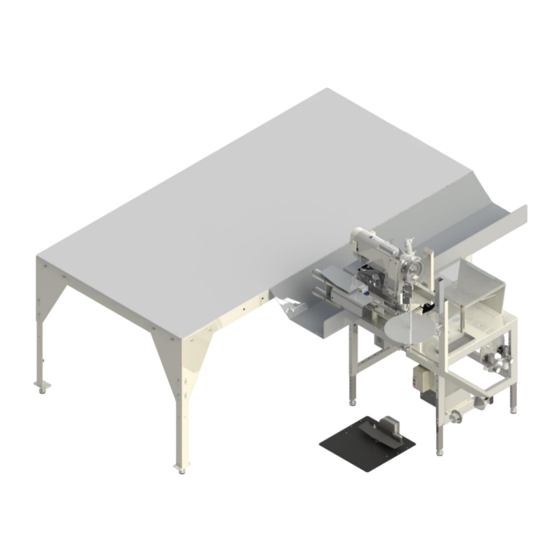
Page 57: 11339Hfs88 Main Assembly
Technical Manual & Parts Lists 11339HFS88 Main Assembly AAC Drawing Number 9001294 Rev 1 QTY PART # DESCRIPTION AR 11344S88PAR PARAMETER DOCUMENT Page 12 Page 1335-816 ROD,SS, 1/2 X 15.0 L 1337A-160 AIR TABLE ASSY,SINGLE TBL Page 55 Page 1338-022 TRAY, BORDER 1338-023 SPACER, BORDER TRAY... - Page 58 Technical Manual & Parts Lists...
-
Page 59: 1337A-160 Air Table Assembly
Technical Manual & Parts Lists 1337A-160 Air Table Assembly AAC Drawing Number 1337296 Rev 8 PART# DESCRIPTION 1335-159 ACCESS COVER 1337135 BLOWER ASSY 1337A-0161 ANGLE, CORNER 1337A-0163 WELDMENT, LEG, TABLE 1337A-150 AIR TABLE ASSY K-235 CONNECTOR,ROMEX,1/2" MMFB4444 FOOT, RUBBER NNH1/2-13 NUT,HEX,1/2-13 SSHC01048 1/4-20 X 3/4 HEX CAP... - Page 60 Technical Manual & Parts Lists...
-
Page 61: 1338-2000 Edge Guide Assembly
Technical Manual & Parts Lists 1338-2000 Edge Guide Assembly AAC Drawing Number 192042B Rev 3 QTY PART # DESCRIPTION 1278-6690 Nut Plate 1278-6942 Rod, Eye Mount 12787-1620 Standoff, Pivot 12787-1632 Standoff 12787-1634 Standoff, 2.5L 132556-511 Motor Mount 132556-513 Pivot Arm 1338-001 Mount Plate 1975-213... - Page 62 Technical Manual & Parts Lists...
-
Page 63: 1338-3000 Touch Switch Assembly
Technical Manual & Parts Lists 1338-3000 Touch Switch Assembly AAC Drawing Number 192043B Rev 1 NO QTY PART # DESCRIPTION 1 1335-320C ROD, 3/8 X 9 2 1335-816 ROD, 1/2 X 13.31 1 1338-008 FRAME, ROLL HOLDER 1 1338-027 SENSOR BRKT 1 1338-028 RING, TAPE GUIDE 1 13453385... - Page 64 Technical Manual & Parts Lists...
-
Page 65: 1338041 Front Roller Assembly
Technical Manual & Parts Lists 1338041 Front Roller Assembly AAC Drawing Number 1338041 Rev 0 QTY PART # DESCRIPTION 1338-004 ROD,S/S,1/2X9.00 1338-005 PLATE,ROLLER MNTNG,FRONT 1338-030 COVER, MOTOR 33005671 ROLLER,1.90 OD, 1.59 ID CCCL8F CLAMP COLLAR- 1/2 SSBC98024 10-32 X 3/8 BUTTON CAP SC SSSC01032 1/4-20X1/2 SOC CAP WWL1/4... - Page 66 Technical Manual & Parts Lists...
-
Page 67: 1344016 Console Assembly
Technical Manual & Parts Lists 1344016 Console Assembly AAC Drawing Number 1344016 Rev 8 PART# DESCRIPTION PART# DESCRIPTION 199-EC-13C H/D MATTRESS AAQME-4-8 ELBOW,QUICK AAQME-5-8 QUICK MALE 0211-209 PLATE,NUT,10-32 0211-702C CABLE,POS.SENSOR AAQMF-144 6-STATION AIR AAQPP-11 PLUG, QUICK 3/8 1335-408 STUD, THREADED AAV125B PILOT VALVE 1337-4100B... - Page 68 Technical Manual & Parts Lists...
-
Page 69: 1338046 Sewing Head Assembly
Technical Manual & Parts Lists 1338046 Sewing Head Assembly AAC Drawing Number 1338046 Rev 4 QTY PART # DESCRIPTION 1315507 BRACKET, CYLINDER 1317307 CYLINDER END, FOOT LIFT 1344025 BRKT, GUIDE MOUNT 1344028 BRKT, CYLINDER MOUNT 1345230 PLATE, BED, RIGHT AR 199-EC-13C H/D MATTRESS BINDER W/CRD AA198RA508 FLOW CONTROL,5/32 X 1/8"... - Page 70 Technical Manual & Parts Lists...
-
Page 71: 1339-1500 Pneumatic Panel Assembly
Technical Manual & Parts Lists 1339-1500 Pneumatic Panel Assembly AAC Drawing Number 192944B Rev 0 QTY PART # DESCRIPTION 0411-071 REGULATOR BRKT 1338-024 PANEL AA198-5102 REGULATOR AAEVQZ2121 VALVE AAQME-4-8 QUICK MALE ELBOW AAQPP-07 QUICK PLUG AAQPR-5-4 QUICK REDUCER FF264-311 WAGO, SINGLE FF264-341 WAGO, DUAL FF264-371... -
Page 72: 1337135 Blower Assembly
Technical Manual & Parts Lists 1337135 Blower Assembly AAC Drawing Number 1337135 Rev2 NO. QTY PART # DESCRIPTION NO. QTY PART # DESCRIPTION 1337116 ADAPTOR, BLOWER SSFS98048 #10-32 X 3/4, FLAT SLOT 1337133 SPACER, BLOWER ASSY SSMBK13 KNOB,BLACK PLASTIC 1337134 GRILL,BLOWER INLET SSSC90016 #8-32 X 1/4 SOC CAP SC... - Page 73 Technical Manual & Parts Lists...
-
Page 74: 1344S88-Pd Pneumatic Diagram
Technical Manual & Parts Lists 1344S88-PD Pneumatic Diagram 125628B... -
Page 75: 1344S88-Wd Wiring Diagram
Technical Manual & Parts Lists 1344S88-WD Wiring Diagram 125629B... - Page 76 Atlanta Attachment Company (AAC) Statement of Warranty Manufactured Products Atlanta Attachment Company warrants manufactured products to be free from defects in material and workmanship for a period of eight hundred (800) hours of operation or one hundred (100) days whichever comes first. Atlanta Attachment Company warrants all electrical components of the Serial Bus System to be free from defects in material or workmanship for a period of thirty six (36) months.
- Page 77 Declaración de Garantia Productos Manufacturados Atlanta Attachment Company garantiza que los productos de fabricación son libres de defectos de mate-rial y de mano de obra durante un periodo de ochocientos (800) horas de operación o cien (100) días cual llegue primero.
- Page 78 Atlanta Attachment Company 362 Industrial Park Drive Lawrenceville, GA 30046 770-963-7369 www.atlatt.com Printed in the USA...
Need help?
Do you have a question about the 1339HFS and is the answer not in the manual?
Questions and answers