
Related Manuals for Atlanta Attachment Company 1335ETA


Summary of Contents for Atlanta Attachment Company 1335ETA
- Page 1 1335ETA Modelo Revision 2.1 June 2023 (wr) Technical Manual & Part Lists Atlanta Attachment Co. 362 Industrial Park Drive Lawrenceville, GA 30046 USA +1 (770-963) 7369 www.atlatt.com...
- Page 3 Company. In addition to any confidentiality and non-disclosure obligations that currently exist between you and Atlanta Attachment Company, your use of these materials serves as an acknowledgment of the confidential and proprietary nature of these materials and your duty not to make any unauthorized use or disclosure of these materials.
-
Page 4: Table Of Contents
Contents CONFIDENTIAL AND PROPRIETARY INFORMATION ............0 CONTENTS ..........................1 IMPORTANT SAFETY INSTRUCTIONS ..................4 ATTENTION: I T IS IMPORTANT THAT THE MACHINE TECHNICIAN READ THIS MANUAL AND BE FAMILIAR WITH ALL FUNCTIONS AND SAFETY CONCERNS OF THE UNIT BEFORE INSTALLING AND OPERATING AINTENANCE . - Page 5 Square Corner Settings, Page 1..................... 27 Round Corner Settings, Page 2 ....................27 Miscellaneous Settings, Page 3 ....................27 PLC Outputs Page 1 ......................28 PLC Inputs Page 1 ........................ 28 Language Selection ......................28 2.4....................... 29 REPARATION FOR EWING Threading the Sewing Head ....................
- Page 6 1336002 CONTROL BOX ......................84 1336010 PLC TOUCH SCREEN ....................86 1335MF-PD PNEUMATIC DRAWING..................87 1335MPLC-WD1 WIRING DIAGRAM ..................88 1335MPLC-WD2 WIRING DIAGRAM ..................89 ATLANTA ATTACHMENT COMPANY (AAC) STATEMENT OF WARRANTY ....... 90 : ........................90 ERMS AND ONDITIONS ..........................90 OVERED ........................
-
Page 7: Important Safety Instructions
Installation Important Safety Instructions This part of the Instruction Material is provided for the safe use of your equipment. It contains important information to help work safely with the unit and describes the dangers inherent in machinery. Some of these dangers are obvious, while others are less evident. -
Page 8: Should Only Be Performed By Trained And Qualified Personnel
Installation ATTENTION: It is important that the machine technician read this manual and be familiar with all functions and safety concerns of the unit before installing and operating. Maintenance should only be performed by trained and qualified personnel. The Instruction Material should always be kept near the machine so that it is accessible to all concerned. - Page 9 Installation A Word to the Operator The greatest danger inherent in our machines is that of fingers, hands or loose clothing being drawn into a machine by live, coasting or rotating tools or assemblies or of being cut by sharp tools or burned by hot elements.
-
Page 10: Important Notices
Installation Protective Eyewear Protective eyewear that has been tested by the local authorities should be worn whenever there is a possibility of loose or flying objects or particles such as when cleaning the machine with compressed air. Tools Always count the number of tools in your possession before starting work on the machine. This will allow you to check that no tools have been left behind inside the machine. - Page 11 The packaging and machine must immediately be examined for signs of damage in transit. Such damage must be reported to the shipper/transporter within the applicable time limits. Contact Atlanta Attachment Company and/or your transport insurer immediately, if signs of damage are visible. Never operate a damaged machine...
- Page 12 Installation Interim Storage If the machine has to be stored temporarily, it must be oiled or greased and stored in a dry place where it is protected from the weather in order to avoid damage. A corrosion-inhibiting coating should be applied if the machine must be stored for a longer period of time and additional precautions taken to avoid corrosion.
-
Page 13: Maintenance
Installation Maintenance General Safety Instructions The machine shall be switched off, come to a standstill, and be secured so that it cannot be switched on again inadvertently before starting any maintenance work whatsoever. Use proper lockout/tagout procedures to secure the machine against inadvertent startup. Remove any oil, grease, dirt, and waste from the machine, particularly from the connections and screws, when starting the maintenance and/or repair work. - Page 14 Installation voltage release in the event of an emergency. The working area should be cordoned off and marked by a warning sign. Only use electrically insulated tools. Ventilation/Hazardous Gases It is the end user’s responsibility to ensure adequate ventilation is provided to exhaust any and all noxious or hazardous gases that may be present in the working environment.
- Page 15 Installation Safety Precautions Safety should be a constant concern for everyone. Always be careful when working with this equipment. While normal safety precautions were taken in the design and manufacture of this equipment, there are some potential safety hazards. Everyone involved with the operation and maintenance of this equipment should read and follow the instructions in this manual.
-
Page 16: Instalation
Installation 1. INSTALATION CAUTION: It is important that the machine technician read this manual and be familiar with all the safety functions and concerns of the unit before installing and operating. Maintenance should only be carried out by trained and qualified personnel. It is important that the operator of the machine read this manual and be familiar with all the functions and safety concerns of the unit before operating. -
Page 17: Technical Data
Installation 1.2. Technical Data 1.3. Top View The top view of the machine will depend on the accessories shipped. Next, graph of different configurations Leave enough free space around to be able to open all the doors and have access for Maintenance. -
Page 18: Machine Identification Tag
Installation 1.4. Machine Identification Tag The identification of the machine is located at the top of the table behind the sewing head. Its content is the machine class and the Serial Number. Ex: 218427031707 The serial number is divided as follows: The first number identifies the order number, 218427 The next number of the month of manufacture, (03) The next number of the year of manufacture, (17) -
Page 19: Types Of Machines & Subclasses
Installation 1.6. Types of Machines & Subclasses... -
Page 20: Assembly
Installation 1.7. Assembly Remove all shipping belts from the machine. Inspect the machine for any damage that may have occurred during shipment. If damage is found, report this immediately to your supervisor. Document the damage and provide details and photographs. Place the machine in the desired location on a reasonably level and stable floor. -
Page 21: Sewing Pedal
Installation 3. Sewing Pedal Connect the sewing pedal cable to the Efka motor cable. 4. Thread Cone Stand Assemble the thread cone stand and adjust as follows. El centro del cono de hilos “A” debe encontrarse en línea con el punto de enhebrado “B”... -
Page 22: Pneumatic
Installation 2. . Pneumatic WARNING: Some moving parts can be activated when opening the valve. Only compressed, dry and filtered air should be used. Make sure that the air pressure always stays within the specified ranges, otherwise, faults can occur. Feed a minimum 3/8- inch diameter pipe to the air inlet connector with a pressure greater than 80 psi (6 bars) and a minimum flow of 2 SCFM per minute. -
Page 23: Operation
Operation 2. Operation 2.1. Parts and Components 1.- Main switch 6.- Material Tensión roller 11.- Fabric Guide 2.- Touch screen 7. Thread Stand and guider 12.- Control box 3.- Touch sensor 8.- Edge or bellows roll 13.- Step Motor Drive Box holder 4.- Air Regulators 9.- Sewing head... -
Page 24: Main Switch
Operation 1. Main Switch Located at the bottom left of the machine table. It has a lock out latch to prevent activation when maintenance work is carried out. The black button starts the machine and the red one stops 2. Touch Screen Located on the right side of the machine. -
Page 25: Material Support Roller
Operation 5. Sewing Foot Pedal It controls the sewing speed. By pressing it on the right side the sewing machine is activated and starts sewing. The more you press, the high the sewing speed is reached. If the Left side is pressed, the sewing foot will raise. 6. -
Page 26: Sewing Head
Operation 9. Sewing head The 1335ETA model is normally delivered with the Typical brand 401 two-thread chainstitch sewing head. With Puller drive roller behind the foot. 10. Material Guide The right side of the edge guide has fixed guides for the right edge of the border. -
Page 27: Power Up Sequence
Operation 2.2. Power Up Sequence Press the power button “A” and the display “C” will illuminate proceeding to the power cycle. NOTE: The power button of the Efka box must be in the on position and the internal light of the button must always be First, a screen with the Atlanta Attachment logo appears on monitor “C”. -
Page 28: Description Of Screens
Operation 2.3. Description of Screens... -
Page 29: Starting Screen
Operation 1. Starting Screen From this screen you can select, Manual mode Automatic mode Round corners Square Corners System information Pages of Inputs and Outputs Ruffler Parameter Settings Language Page 2. Manual Mode Its function is to use the sewing machine in manual mode. In this mode, the Ruffler system will not work, and the sewing head will work like a regular sewing machine. -
Page 30: Machine Ready
Operation f. Machine Ready It will be lit green if the seams conditions are present. g. Navigations Buttons: They are at the bottom of the screen and allow the operator to move to other screens. 4. System Information It shows the data of the machine model, the voltage, the air pressure, and the version of the program. -
Page 31: Plc Outputs
Operation 8. PLC Outputs Page 1 They show the status of all the outputs of the microprocessor. This area is usually reserved for technicians. 9. PLC Inputs Page 1 They show the status of all microprocessor inputs. This area is used reserved for technicians. 10. -
Page 32: Preparation For Sewing
Operation 2.4. Preparation for Sewing 1. Threading the Sewing Head With the machine on, press the touch sensor, remove the cloth guide. Follow the threading instructions in the sewing head manual. 2. Loading Edge Roll or Bellows Remove the safety pin from the roll support arm and extend it out. -
Page 33: Sewing Cycle
Operation 3. Adjusting the Media Roll Guide Insert the roll tab through the top of the media roll guide. Continue feeding the roll through the second sheet of the media roll guide. Adjust the left guides “A” to make a tight fit to the width of the tab. - Page 34 Operation Lower the Fabric guide securing the non-woven and then pull border material towards the presser foot. Position the beginning of the roll pass the needle. Press the finger/touch sensor to lower the material guide. Press the sewing pedal and start the sewing cycle. Continue sewing until the lower sensor detects the corner.
- Page 35 Operation Depending on the selected program, make the corner folds and repeat the cycle until the last corner. Continue sewing, stopping just short of the lower material guide. Press the touch sensor and raise the roll guide. Remove the beginning of the border material from the shirring guide Remove the non-woven from the guide.
- Page 36 Operation Remove some edge of the roll guide. Cut the edge at the height of the roll guide. Raise and Swing-out the border material guide by pressing the touch sensor and proceed to final edge stitching.
-
Page 37: Operation With Rounded Corners
Operation 1 Operation with Rounded Corners Automatic Mode selection on the Main screen The Automatic mode operation screen is displayed. Selection “Round Corner”. Sew the non-woven panel to the corner making sure that your hands are not in the way of the electric eye which is mounted under the table and that you should “see”... -
Page 38: Operation With Square Corners
Operation 2 Operation with Square Corners Automatic Mode selection on the Main screen The Automatic mode operation screen is displayed. Select “Square Corner” . Sew the non-woven panel in the corner making sure that your hands are not in the way of the electric eye which is mounted under the table and that you should “see”... -
Page 39: Preventive Maintenance 8 Hours
Operation 2.6. Preventive Maintenance 8 Hours Preventative Maintenance Modelo: 11335ETA Required Material Serial: oiler Operation: Pleating / Ruffling Machine sewing machine oil Sewing head: clean rags Serial: compressed air Needle: SN62x5924 22-180 Before starting the working day "With the Machine Off " .Wipe with a clean cloth Remove any accumulated dirt or debri .- check for wáter or oil residue and... -
Page 40: Service
The following references provide information about the LOTO process. Equipment Energy Control Procedure Lockout/Tagout Program Description: Ruffling Machine Model: 1335ETA Manufacture Atlanta Attachment Locati Energy Location Magnitude Control Method... -
Page 41: Important Information
Service 3.2. Important Information It is important that the machine technician read this manual and be familiar with all functions and safety concerns of the unit before installing and operating. Maintenance should only be performed by trained and qualified personnel. 3.3. -
Page 42: Calibration And Position Of Ruffling Blade
Service 4. Calibration and Position of Ruffling Blade Loosen the two screws on the cover of the stepper motor assembly. Remove the cover by lifting. Locate the two proximity switches to the right of the ball screw. The rear sensor “A” is the start sensor, and the front sensor “B”... -
Page 43: Fold Size
Service Adjust this height through the “C” screws at the base of the cylinder. In the same position adjust the depth so that the front edge of the blade is slightly in front of the needle. To make this adjustment it is necessary to modify the position of the front sensor “B”... -
Page 44: Separator Sheet
Service 6. Separator Sheet The spacer blade is part of the corrugated assembly and is mounted to the bed plate of the sewing head on its own oscillation bracket. The spacer sheet allows the corrugated sheet to pinch the edge material between it and the spacer sheet and push the material under the foot without folding the nonwoven panel. - Page 45 Service 8. Folder or Border Material Guide The function of the guide is to keep the fabric aligned with the sewing machine during the sewing cycle. It has a series of spacers "A" to separate the top and bottom of the guide and thus allow the material to move freely.
-
Page 46: Reference Table For Material Thickness / Folder Spacers
Service 9. Reference Table for Material Thickness / Folder Spacers... -
Page 47: Pneumatic Adjustments
Service 3.4. Pneumatic Adjustments For more detailed adjustments refer to the pneumatic diagram at the end of this manual as well as to the individual manuals of the manufacturers of the components attached to the accessory box, such as sewing head and motors. The main pneumatic components of the machine are the following: 1.Main pressure regulator... -
Page 48: Main Pressure Regulator
Service 1. Main Pressure Regulator Located on the right side of the regulators. It is responsible for the general pressure of the machine. During the sewing cycle, you should not lower the pressure on the pressure gauge. Factory Pressure 70 PSI The pneumatic maintenance units are composed of three elements: a. -
Page 49: Presser Foot Pressure Regulator
Service 3. Presser Foot Pressure Regulator Located on the left side of the regulators. It is responsible for the pressure of the presser foot when sewing. During the sewing cycle it is activated until the cycle of the ruffles is started. -
Page 50: Valve Block
Service 7. Valve Block. Responsible for activating the cylinders of the machine. It is located on the inside of the control box. The solenoid valves are electrically activated (24 VDC) and can be mechanically activated directly on the valve body by pressing the manual blue actuators. -
Page 51: Puller Lifting Piston
Service 11. Puller Lifting Piston Responsible for lifting the fabric. It has two flow regulators to limit the speed of movement. This must be harmonic without hitting the end of the stroke. Apart from the electric command also has a pneumatic valve for manual activation of the same. -
Page 52: Electrical Adjustments / Settings
Service 3.5. Electrical Adjustments / Settings The main electrical components of the machine are the following: 1.-Main Switch. 6.- Efka Sewing Motor 11.-Material Optical Sensor 2.-Touch Screen 7.-Step Motor 12.-Guide Position Sensor 3.-Control Box 8.-Control Box Step Motor 13.-Sensor Limit Switch 4.-Control Box Efka Motor 9.- Touch Activator 14.- Sensor Limit Switch... -
Page 53: Main Switch
Service 1. Main Switch Located in the lower left part of the machine table. It has a safety foil to prevent ignition when maintenance work is performed. The black button turns on the machine and the red button stops it. In case of power loss the switch is automatically deactivated. -
Page 54: Plc Replacement
Service 4. PLC Replacement HOW TO CHANGE PLC IN 1335MGCA-SU OR 1335ETA: 1) VERY IMPORTANT: Record any machine settings on the settings pages (3 pages total) 2) Remove power from the machine a) Turn off power to machine b) Disconnect power plug at... - Page 55 Service 6) Carefully remove the top terminal block from the PLC base and then remove the bottom terminal block from the PLC base. (See pictures below) 7) Carefully remove cassette from PLC base (see left side picture below) 8) Pull down on the blue clip on the bottom side of the PLC base until it clicks. Raise up on the bottom side of the PLC base and pull outward away from the din rail.
-
Page 56: Efka Motor Control Box
Service 5. Efka Motor control Box The Efka control has been programmed to operate the sewing head in conjunction with the folder. The maximum sewing speed has been programmed for 3,500. The maximum sewing speed can be temporarily reduced by keeping the button pressed. "-"... - Page 57 Service...
-
Page 58: Sewing Pedal
Service 7. Sewing Pedal It controls the sewing speed. When pressed to the right side the sewing machine is activated and starts sewing. The more you push the more speed you reach. If pressed to the left side the presser and the roller pull 8. -
Page 59: Small Switches (Sw1)
Service 1. Small Switches (SW1) Internally the control box contains small switches which should be in the following position. This adjustment comes from the factory, but in case of replacement of the box you should check. Switch 1: Controls the motor rotations. CW: Clockwise. CCW: Against the direction of the clock. -
Page 60: Hand Wheel Sensor
Service 12. Hand Wheel Sensor The hand wheel sensor (1) is mounted on the top of the table, behind and to the right of the sewing head. The hand wheel sensor (1) reads a piece of the reflective tape located on the pulley disk (2). The hand wheel sensor is responsible for reporting to the Efka engine that the sewing head is sewing at the set RPM, stitch counting for all counters, and for the position of the needle when it stops. -
Page 61: Edge Guide Position Sensor
Service 16. Edge Guide Position Sensor It is activated when the edge guide is anchored in its working position. If this sensor is not activated, seam ruffles will not be produced. 17. Adjustable Stroke Sensor of the Stepper Motor Shaft The stroke sensor "A"... -
Page 62: Programming
Service 3.6. Programming 1 Input and Output Elements Pressing the key gives access to the input and output elements. a. Output Screen Page 1 They show the status of all the outputs of the microprocessor. By pressing the white squares some of them will be able to activate the valves When pressing the sewing pedal or performing any sewing operation, the squares will be activated showing their... -
Page 63: Settings Screen Path
Service d. Settings Screen Path Pressing the settings symbol accesses the Settings screens... -
Page 64: Programming A Square Corner
Service e. Programming a Square Corner. Details of each of the steps correspond to the settings during the sewing cycle. This is the stitch count (1-9 stitches) from the end of the first set of ruffles until the needle stops to rotate the material. - Page 65 Service Sets the number of stitches sewn in each pleat and is adjusted according to the size of the pleat. There should be enough stitches to sew the folded edge of each pleat. To change the values, press the dark field in the column of numbers the value you want to change.
-
Page 66: Programming A Round Corner
Service f. Programming a Round Corner. Details of each of the steps correspond to the settings during the sewing cycle. Sets the stitch count for the Slow Start function after the last fold. This reduces the sewing speed for a few stitches to help feed the material to the pinch roller before the machine goes to high speed. - Page 67 Service To change the values, press the dark field in the column of numbers the value you want to change. Screen will appear. Type the Key Supervisor Level: 2222 Technical Level: 3333 Press ENTER The screen appears with a padlock on the right a key in case of technical service level.
-
Page 68: Maintenance
Service 3.7. Maintenance It is important that the machine technician read this manual and be familiar with all features and safety concerns of the unit before installing and operating. Maintenance should only be performed by trained and qualified personnel. 1. General Safety Instructions Maintenance should only be performed by trained and qualified personnel. -
Page 69: Faults
Service 3.8. Faults Problema Causa: Acción Correctiva Machine does not turn on Electrical fault Check that the main switch and that of the Efka motor box are working. Skip Stitch Thread Tensions Check the threading of the threads and the correct tension of the same. - Page 70 Service...
-
Page 71: High Mortality Parts Kit
3.9. High Mortality Parts Kit The machine is offered as an option with a set of high mortality parts recommended for the natural consumption of the machine. The content of the kit is as follows: Part Number: SP1335ET Item Part Number Description 022400015 Feed tooth screw 11 / 64-40 x 10 s... -
Page 72: Training
3.10. Training Actividad Tiempo Security instructions 5 min Use of the Manual 5 min FACILITY 2 hr. ON / Off Switch 20 min Control Panel PREPARATION 1 hr. Threading of machine Material roll position and adjustment Tension adjustment. Roll and panel guide adjustments. Folder Calibration SEWING 4 hr... -
Page 73: Drawings And Parts Lists
Atlanta Attachment Company. In addition to the obligations of confidentiality and nondisclosure that currently exist between you and Atlanta Attachment Company, your use of these materials serves as an acknowledgment of the confidential and proprietary nature of these materials and... -
Page 74: 11335Eta Ruffler, Workstation, Economy, Plc
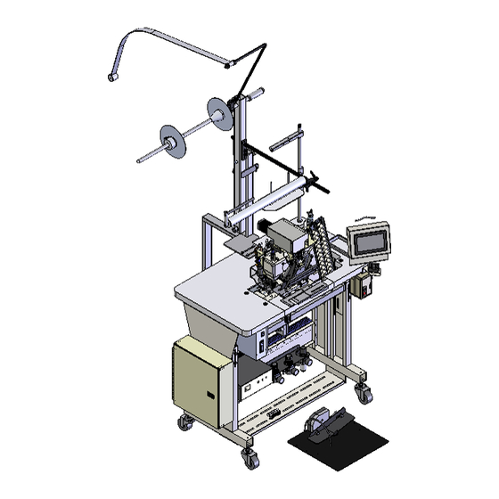
11335ETA Ruffler, Workstation, Economy, PLC AAC Drawing Number 9007760 Rev 0... -
Page 75: 1335930 Roll Holder Assembly, Overhead
1335930 Roll Holder Assembly, Overhead AAC Drawing Number 1335930 Rev 4... -
Page 77: 1336004 Console Base, Plc
1336004 Console Base, PLC AAC Drawing Number 1336004 Rev 0 ITEM QTY PART NUMBER DESCRIPTION 1325144 SEW HEAD SUBASSEMBLY 1335MF-PD DIAGRAM, PNEUMATIC 1335MPLC-WD1 WIRING DIA., PLC 1335MPLC-WD2 WIRING DIA., POWER 1336012 STAND / MOTOR ASSY- TYP GK-321 1959-112 2 POS THREAD PLATE ASSY 26151 TOOL TRAY, 1X3.5X9 THREAD STAND, 2 THREAD... -
Page 78: 1325144 Sew Head Assembly
1325144 Sew Head Assembly AAC Drawing Number 1325144 Rev 1... -
Page 80: 1325148 Ruffler Assembly, Typ
1325148 Ruffler Assembly, TYP AAC Drawing Number 1325148 Rev 0... - Page 81 1325148 parts list I TEM I TEM QTY PART NUMBER DESCRI PTI ON QTY PART NUMBER DESCRI PTI ON 1278-7055B PROX. SWI TCH W/ PLUG 12" LG MM8FM JOI NT,UNI VERSAL,MOD TAPE, UHMW, 1" W X .01 1335M-001 BRACKET, STOP, PRX SWI TCH 11* MM130-10A1 1335M-2006 BLOCK, NUT TRUNI ON...
-
Page 82: 1325160 Puller Sub-Assembly
1325160 Puller Sub-Assembly AAC Drawing Number 1325160 Rev 2 Notes: Arrange the components as shown(apply Teflon based grease to the bearings and a small amount to all mating thrust washer surfaces). Screw in the small set screw to leave about3/8” of threads in the axle on the right side. Install and tighten the large set screw(21) against the small set screw to form a stud Install and tighten the socket cap screw and the lock washer on the left side. - Page 83 1325160 parts list ITEM QTY. PART NUMBER DESCRIPTION 65375 UPPER ROLLER LIFT PIN 95027 RING,RETAINING,YAMATO 1325157 PULLER BRACKET 1325158 YOKE, PULLER-HD 1325161 STRIPPER PLATE, EXTENDED 1325162 STRIPPER PLATE,EXTENDED 1334056 PULLER LIFT LINK,11-64-40 1335397 PULLER ROLLER, HD, 2002MG 1335399 SHAFT, PULLER, HD 1335400 WASHER, HUB CAP, 1/4 1335414...
-
Page 84: 1325173 Foot Pressure Assembly
1325173 Foot Pressure Assembly AAC Drawing Number 1325173 Rev 0 PART ITEM QTY. PART NUMBER DESCRIPTION ITEM QTY. DESCRIPTION NUMBER 1325171 MTG BRKT, FOOT LIFT AAFP18 MUFFLER,1/8 NPT, BRONZ 1335M-108 LEVER,FOOT PRESSURE NNJ5/16-24 NUT,JAM,5/16-24 AA198RR508 FLOW CONTROL,5/32 X 1/8" NNK1/4-20 NUT,KEP,1/4-20 AAC7DP-.5 CYLINDER,AIR,DA... -
Page 85: 1336012 Stand And Motor Assembly, Typ Gk-321
1336012 Stand and Motor Assembly, TYP GK-321 AAC Drawing Number 1336012 Rev 1... - Page 86 1336012 parts list...
-
Page 87: 1336002 Control Box
1336002 Control Box AAC Drawing Number 1336002 Rev 4... -
Page 89: 1336010 Plc Touch Screen
1336010 PLC Touch Screen AAC Drawing Number 1336010 Rev 1... -
Page 90: 1335Mf-Pd Pneumatic Drawing
1335MF-PD Pneumatic Drawing AAC Drawing Number 125860A Rev 10... -
Page 91: 1335Mplc-Wd1 Wiring Diagram
1335MPLC-WD1 Wiring Diagram AAC Drawing Number 125469D Rev 3... -
Page 92: 1335Mplc-Wd2 Wiring Diagram
1335MPLC-WD2 Wiring Diagram AAC Drawing Number 125470D Rev 2... -
Page 93: Atlanta Attachment Company (Aac) Statement Of Warranty
Atlanta Attachment Company (AAC) Statement of Warranty Atlanta Attachment Company warrants manufactured products to be free from defects in material and workmanship for a period of eight hundred (800) hours of operation or one hundred (100) days whichever comes first. Atlanta Attachment Company warrants all electrical components of the Serial Bus System to be free from defects in material or workmanship for a period of thirty-six (36) months. - Page 95 Atlanta Attachment Company Inc. 362 Industrial Park Drive Lawrenceville, GA 30046 USA Teléfono: +1 (770) 963-7369 www.atlatt.com Printed in the USA Digital version of this Manual is available at: http://atlatt.com/tech_manuals.php...
Need help?
Do you have a question about the 1335ETA and is the answer not in the manual?
Questions and answers