
Related Manuals for Atlanta Attachment Company 1337DLA


Summary of Contents for Atlanta Attachment Company 1337DLA
- Page 1 1337DLA Model Revision 0 Created September 19, 2024(wr) Technical Manual & Parts Lists Atlanta Attachment Company 362 Industrial Park Drive Lawrenceville, GA 30046 770-963-7369 • www.atlatt.com...
- Page 3 Attachment Company. In addition to any confidentiality and non-disclosure obligations that currently exist between you and Atlanta Attachment Company, your use of these materials serves as an acknowledgment of the confidential and proprietary nature of these materials and your duty not to make any unauthorized use or disclosure of these materials.
-
Page 4: Table Of Contents
Technical Manual & Parts Lists Contents Important Safety Instruction ........................1 Liability ..............................2 Safety Equipment on the Machines ......................3 Protective Eyewear ............................. 4 Important Notices............................5 Maintenance ..............................7 Repair ................................8 A Word to the End User..........................9 Safety Precautions ............................ - Page 5 1337779 PNEUMATIC PANEL ..................... 70 97-1700A TOUCH SCREEN ASSEMBLY ..................... 71 1337-600PD PNEUMATICS DIAGRAM ....................72 1337DLA-WD WIRING DIAGRAM, COMPLETE ................73 1337DLPAR Efka Parameters ........................74 Atlanta Attachment Company (AAC) Statement of Warranty ..............75 Declaración de Garantía ..........................76...
-
Page 6: Important Safety Instruction
Mandatory Information All persons operating and/or working on the 1337DLA , should read and understand all parts of the Safety Instructions. This applies, in particular, for persons who only operate and/or work on the unit occasionally (e.g. for maintenance and repair). Persons who have difficulty reading must receive particularly thorough instruction. -
Page 7: Liability
Technical Manual & Parts Lists Liability The machine should only be operated when in perfect working order, with due regard for safety and the potential dangers, as well as in accordance with the Instruction Material. Faults and malfunctions capable of impairing safety should be remedied immediately. We cannot accept any liability for personal injury or property damage due to operator errors or non-compliance with the safety instructions contained in this booklet. -
Page 8: A Word To The Operator
Technical Manual & Parts Lists A Word to the Operator The greatest danger inherent in our machines: is that of fingers, hands or loose clothing being drawn into a machine by live, coasting or rotating tools or assemblies or of being cut by sharp tools or burned by hot elements. LWAYS BE CONSCIOUS OF THESE DANGERS Safety Equipment on the Machines All machines are delivered with safety equipment, which shall not be removed or... -
Page 9: Protective Eyewear
Technical Manual & Parts Lists Protective Eyewear Protective eyewear that has been tested by the local authorities should be worn whenever there is a possibility of loose or flying objects or particles such as when cleaning the machine with compressed air. Tools Always count the number of tools in your possession before starting work on the machine. -
Page 10: Important Notices
Technical Manual & Parts Lists Important Notices Reporting and Fighting Fires Read the instructions posted in the factory with regard to reporting fires and the emergency exits. Make sure you know exactly where the fire extinguishers and sprinkler systems are located and how they are operated. -
Page 11: Transport Damage
Technical Manual & Parts Lists - Kinetic energy - Note that some motors or spindles, for example, may continue to run or coast run on after being switched off. - Potential energy - Individual assemblies may need to be secured if necessary for repair work. Delivery of the Machine/Packaging Note any markings on the packaging, such as weights, lifting points and special information. -
Page 12: Maintenance
Technical Manual & Parts Lists Protect against influences from the surroundings: no structure-borne vibrations, no grinding dust, or chemical vapors. Protect against unauthorized access. Ensure that the machine and accessories are set up in a stable position. Ensure easy access for operation and maintenance (Instruction Manual and layout diagram); also verify that the floor is strong enough to carry the weight of the machine. -
Page 13: Repair
Technical Manual & Parts Lists Repair Replacement Parts We cannot accept any liability whatsoever for damage due to the use of parts made by other manufacturers or due to unqualified repair or modification of the machine. Repair, Electrical The power supply must be switched off (master switch off) and secured so that it cannot be switched on again inadvertently before starting any work on live parts. -
Page 14: A Word To The End User
Technical Manual & Parts Lists A Word to the End User The end user has sole responsibility to enforce the use of safety procedures and guards on the machine. Any other safety devices or procedures due to local regulations should be retrofitted in accordance to these regulations and/or the EC Directive on the safety of machines. -
Page 15: Machine Overview
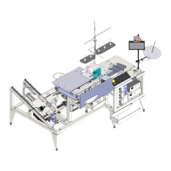
Technical Manual & Parts Lists Machine Overview The 11337DLA is a semi-automatic unit designed to assemble prepared skirt material to mattress pads. This unit utilizes premade skirt material in roll format with the elastic already installed. This roll is installed under the machine and held by a friction brake to maintain a constant tension on the skirt. The operator presents mattress pads one at a time to sew the pad and skirt together. -
Page 16: Major Machine Components
Technical Manual & Parts Lists Major Machine Components All directions (front, back, right or, left) are assumed to be from the front facing the unit unless otherwise stated ON / OFF Switch o Basic on / off pushbutton operation for machine power. o The ON button will not energize the machine unless the red EMERCENCY STOP BOTTON (Operator Panel) is in the up position. - Page 17 Technical Manual & Parts Lists o CUT – LARGE YELLOW BUTTON ▪ In Manual Mode the Cut Cycle is activated every time. ▪ In Auto Mode it performs two functions • First Press - Activates the Cut Cycle o Closes Finger Guard o Turns on Cutter Motor o Moves the Cutter Motor to across the material based on a specified amount of time timer controlled by the digit switches(Position 1-2)
-
Page 18: Pneumatic Pressure Panel
Technical Manual & Parts Lists Pneumatic Pressure Panel o SKIRT TENSION – Material Dependent - Controls the force of the Backpressure Roller against the Skirt Roll. If the pressure is tool low the brake could slip on the material resulting in inconsistent tension. -
Page 19: Touch Screen Controls
Technical Manual & Parts Lists Touch Screen Controls Ready Screen Position of Sewing Head Move to Left Move to Right Cut Button Mode Push to Cut elastic Push to Insert elastic Feed Roller Position Push to Open Piece Count Load Roll Cycle... - Page 20 Technical Manual & Parts Lists Manual Button Setup Button Operator level view Head Mechanic or higher-level view...
-
Page 21: Technical Screens
Technical Manual & Parts Lists Technical Screens Show All Settings Advanced Setup System Information... - Page 22 Technical Manual & Parts Lists Security (Levels of Access with Code)
- Page 23 Technical Manual & Parts Lists Advance Manual Page 1 Page 2 Page 3...
- Page 24 Technical Manual & Parts Lists Advanced Settings...
- Page 25 Technical Manual & Parts Lists...
- Page 26 Technical Manual & Parts Lists...
- Page 27 Technical Manual & Parts Lists...
- Page 28 Technical Manual & Parts Lists o STEPPING MOTOR CONTROLLER (SMALL) – Controls side to side motion of the Skirt Position Alignment Mechanism. ▪ Digit Switch (3 position) - These switch have no effect in this model. ▪ Jog Button - DO NOT USE - Drives the Skirt Alignment mechanism to the right in either Auto or Manual Modes.
-
Page 29: Skirt Loading Slide
Technical Manual & Parts Lists Skirt Loading Slide – Inclined sliding mechanism to facilitate the loading and unloading of Skirt Material in a more ergonomic position Back Pressure Assembly – Located on the Skirt Loading Slide this controls the amount of brake force or “drag” on the Skirt Roll and as a result amount of stretch of the Skirt Material during processing. -
Page 30: Skirt Feeder Mechanism
Technical Manual & Parts Lists Skirt Feeder Mechanism • - Consists of two wide pinch roller connected to a stepping motor that feeds Skirt Material based on the speed of the machine. The speed of the material feed is adjustable to with respect to the Sewing Head speed to help maintain a constant stretch of the Skirt Material Skirt Cut Mechanism... -
Page 31: Scrap Removal System
Technical Manual & Parts Lists Scrap Removal System – The design of the Sewing Head incorporates a cutter to trim the edge of the pad and the skirt material during processing. There is a system to help direct this trim or scrap away from the work area. -
Page 32: Efka Motor Control
Technical Manual & Parts Lists • Efka Motor Control – Check that the On/Off switch on the Efka motor controller is Orange, and that the Display shows the RPM. If not, press the On/Off switch in the down position to turn on. A detailed description for programming the Efka Motor Control is covered in a later section Machine Set Up... -
Page 33: Basic Operation
Technical Manual & Parts Lists • Close Feeder Rollers at Operator Panel • Using Skirt Feed Button feeder some material into the work area to ensure proper feeding without binding. • THREADING SEWING HEAD - Threading, Setup, Maintenance and Operation of the PEGASUS Sewing Head is beyond the scope of this Publication. - Page 34 Technical Manual & Parts Lists • MATERIAL POSITIONING SENSORS ADJUSTMENT This adjustment is product dependent. The Skirt material coming off the supply roll travels under the machine, in front of the first rolling bar, and behind the second one before passing through the feeder pinch rollers and the onto the work surface for processing.
-
Page 35: Electrical
Technical Manual & Parts Lists Electrical It is important that the machine operator read this manual and is familiar with all the functions and safety concerns of the unit before operating. MAIN POWER SWITCH The main power On/Off switch is located under the table and to the right. -
Page 36: Efka Motor Control
Technical Manual & Parts Lists Efka Motor Control– Parameters Parameter Programming Sheet 11337DLA See printable page at end of this manual Front Panel LED's Programming Instructions: 1. Power on holding down the "P" button till "COD" is displayed. LED 1 Off 2. -
Page 37: Programming
Technical Manual & Parts Lists Programming 1) Press and hold the “P” button while turning on the Efka Main Power Switch 2) Once “Code” appears in the display release the “P” button and press the “>>” button. 0000 will appear on the display with the left 0 blinking. - Page 38 Technical Manual & Parts Lists 7) The display will change to “0.4.0.0.” this is a parameter number “400”. Number with the “.” between the digits are parameters. To move to the correct parameter you will press either the “+” or “‐”...
- Page 39 Technical Manual & Parts Lists 10) The display will show “2.9.1.”, this is the next parameter after “290”. You will use the “+” or “-” buttons to advance to the next parameter on the list, and then follow the process in step 9. Continue this until all parameters have been set according to the programming sheet.
-
Page 40: Maintenance
Technical Manual & Parts Lists Maintenance • Four Hours (2 per shift) o Add oil to the upper looper holder and the needle bar. • Daily Check o Open all covers on the sewing head and blow out with compressed air. o Check oil level in machine each morning, prior to start of production. -
Page 41: Assembly Drawings & Parts Lists
Company. In addition to any confidentiality and non-disclosure obligations that currently exist between you and Atlanta Attachment Company, your use of these materials serves as an acknowledgment of the confidential and proprietary nature of these materials and your duty not to make any unauthorized use or... -
Page 42: 11337Da Flanger Assy
Technical Manual & Parts Lists 11337DA FLANGER ASSY AAC Drawing Number 90001026 Rev 0... - Page 43 Technical Manual & Parts Lists...
- Page 44 AT FRONT SHELF 8 x 38.8 1337836 FOOT PEDAL ASSY,EFKA 1337968 CONTROL BOX, GATEWAY, UL COMPLIANT 1337972 DOOR, CONTROL BOX 1337973 PANEL ELEC& PNEU 1337DLA-WD DIAGRAM, WIRING, SBUS 1337DLPAR EFKA PRAMETERS 1959-112 2 POS THREAD PLATE ASSY 1959-161 3 POS THREAD PLATE ASSY. 97-1700A...
-
Page 45: 1337588 Frame With Covers
Technical Manual & Parts Lists 1337588 FRAME WITH COVERS AAC Drawing Number 1337588 Rev 2 NO QTY PART # DESCRIPTION 1337024 MOUNT, AI R TABLE 1337589 FRAME, MAI N FLANGER 1337671 PLATE, SENSOR REFLECTOR 1337764 TOP FRAME AND COVERS 1337793 COVER, FRONT CABI NET 1337794 COVER REAR CABI NET... -
Page 46: 1337672 Sewing Head Carriage
Technical Manual & Parts Lists 1337672 SEWING HEAD CARRIAGE AAC Drawing Number 1337672 Rev 3... - Page 47 Technical Manual & Parts Lists 1337672 parts list ITEM QTY. PART NUMBER DESCRIPTION 0411-128B ISOLATOR MOUNT ASSEMBLY 1337673 PLATE, SEWING HEAD BASE 1337674 PLATE, SEWING HEAD FLOAT 1337675 MOUNT, SEWING HEAD PISTON 1337676 MOUNT, WASTE BIN LOWER 1337677 MOUNT, WASTE FUNNEL 1337829 COVER, BELTS, SEWING HEAD 1337868...
-
Page 48: 1337678 Material Feeder System
Technical Manual & Parts Lists 1337678 MATERIAL FEEDER SYSTEM AAC Drawing Number 1337678 Rev 0... - Page 49 Technical Manual & Parts Lists 1337678 parts list NO QTY PART # DESCRIPTION 4080-4508B CABLE,STEP MOTOR,4 AMP,7' 1337679 FRAME, MATERI AL FEEDER 1337686 FEED ROLLER DRI VE 1337691 PRESSURE ROLLER, FEED 1337705 CUTTER ASSY 1337712 SLOTTED FI NGER GUARD 1337752 SHAFT, ROLLER 1337755 LOWER SENSOR MOUNT...
-
Page 50: 1337686 Feed Roller Drive
Technical Manual & Parts Lists 1337686 FEED ROLLER DRIVE AAC Drawing Number 1337686 Rev 1 ITEM QTY. PART NUMBER DESCRIPTION 1337687 FRAME, DRIVE ROLLER 1337688 ROLLER, DRIVE, FEEDER 1337689 BEARING MNT, DRIVE ROLLER 1337690 MOUNT, STEPPING MOTOR 1337828 ROLLER MOUNT, BACK RIGHT AP-22E-103 STEP MOTOR, 2 AMP BBE2-13... -
Page 51: 1337691 Pressure Roller Feed
Technical Manual & Parts Lists 1337691 PRESSURE ROLLER FEED AAC Drawing Number 1337691 Rev 0... - Page 52 Technical Manual & Parts Lists 1337691 parts list ITEM QTY. PART NUMBER DESCRIPTION 1337692 WELDMENT, CROSSBAR W/JETS 1337694 BEARING MOUNT, DRIVE ROLL 1337697 SPRINGS FLAT 1337698 PLATE, SPRING BACKING 1337699 ROLLER PIVOT BOTTOM 1337700 ROLLER, PRESSURE 1337701 MOUNT CYLINDER / ROLLER 1337702 SHAFT, PIVOT 1337703...
-
Page 53: 1337705 Cutter Assy
Technical Manual & Parts Lists 1337705 CUTTER ASSY AAC Drawing Number 1337705 Rev 1... - Page 54 Technical Manual & Parts Lists 1337705 parts list NO QTY PART # DESCRIPTION 1337706 CYLI NDER MOUNT VERTI CAL 1337707 CYLI NDER MOUNT HORI Z. 1337708 MOUNT, AI R MOTOR 1337709 CUTTER HUB 1337710 CUTTER TOP CAP 1337711 GUARD, CUTTER 1337714 MOUNT CUTTER GUARD 1337827...
-
Page 55: 1337712 Slotted Finger Guard
Technical Manual & Parts Lists 1337712 SLOTTED FINGER GUARD AAC Drawing Number 1337712 Rev 1... - Page 56 Technical Manual & Parts Lists 1337712 parts list ITEM QTY. PART NUMBER DESCRIPTION 1337717 MOUNT, CUTTER BAR MAIN 1337718 CUTTER BAR LOWER 1337719 CUTTER BAR UPPER 1337720 FINGER GUARD 1337721 MOUNT CUTTER BAR 1337722 MOUNT, CYLINDER CLEVIS 1337723 STOP BLOCK 1337724 NUT, DOUBLE 1337725...
-
Page 57: 1337726 Spool Carrier
Technical Manual & Parts Lists 1337726 SPOOL CARRIER AAC Drawing Number 13237726 Rev 1... - Page 58 Technical Manual & Parts Lists 1337726 parts list NO QTY PART # DESCRIPTION 4080-4508B CABLE,STEP MOTOR,4 AMP,7' 1337727 SLI DI NG PLATE, SPOOL 1337734 MOUNT, SENSOR 1337753 CONNECTI ON, CYL - SLI DE 2 1337754 CONNECTI ON, CYL - SLI DE 1 1337809 BACK PRESSURE ASSEMBLY 1337810...
-
Page 59: 1337809 Back Pressure Assembly
Technical Manual & Parts Lists 1337809 BACK PRESSURE ASSEMBLY AAC Drawing Number 1337809 Rev 2... - Page 60 Technical Manual & Parts Lists 1337809 parts list NO QTY PART # DESCRIPTION 1337730 SLIDE, BACK PRESSUSE 1337731 SHAFT MNT, BACK PRESSURE 1337732 SHAFT, BACK PRESSURE 1337733 MOUNT, BRAKE 1337741 END PLATE, BACK PRESSURE 1337742 WELDMENTBACK PRESSURE 1337746 ROLLER, BACK PRESSURE1 1337747 SHAFT, CLUTCH BRAKE 1337748...
-
Page 61: 1337810 Slide Carrier Spool
Technical Manual & Parts Lists 1337810 SLIDE CARRIER SPOOL AAC Drawing Number 1337810 Rev 1... - Page 62 Technical Manual & Parts Lists 1337810 parts list ITEM QTY. PART NUMBER DESCRIPTION 1337728 SLIDER, SPOOL MOUNT 1337729 MOUNT, MOTOR LEAD SCREW 1337735 MOUNT, LEAD SCREW NUT 1337736 SHAFT MOUNT WELDMENT 1337739 COLLAR, SHAFT, SPOOL 1337740 CROSSBAR, SLIDE TRAVEL 1337815 MOUNT, LEAD SCREW BEARNG 1337846 BALL SCREW AND NUT...
-
Page 63: 1337982 Control Panel
Technical Manual & Parts Lists 1337982 CONTROL PANEL AAC Drawing Number 1337982 Rev 0 QTY. I TEM PART NUMBER DESCRI PTI ON 1337771 CONTORL PANEL CASE 1337983 OPERATOR PANEL, SBUS SSBC90016 8-32 X 1/4 BUTTON CAP... -
Page 64: 1337983 Operator Panel
AAC Drawing Number 1337983 Rev ITEM QTY. PART NUMBER DESCRIPTION 1337-011 CABLE, 2 COND TO 4P MOLEX 1337-015 CABLE E-STOP 1337DLA-LAB1 CONTROL PANEL LABEL, SBUS 1337776 CONTROL PANEL COVER EE3X10 BLOCK,P.B. CONTACT, N.O. (GRN) EE800FP-MM65 PUSHBUTTON,22MM,MOM,MUSH, EE1105 SWITCH, ROCKER, 28V ILLUM EEA3L... -
Page 65: 1337800 Parts Shelf
Technical Manual & Parts Lists 1337800 PARTS SHELF AAC Drawing Number 1337800 Rev 0 NO QTY PART # DESCRIPTION 1337799 MOUNT SHELF 1337801 SHELF, PART LONG 1337802 SHELF, PARTS SHORT SSBC90020 8-32X3/8 BUTTON CAP SSSC01024 1/4-20 X 3/8 SOC CAP SC... -
Page 66: 1337818 Leg Assy Pad Corner
Technical Manual & Parts Lists 1337818 LEG ASSY PAD CORNER AAC Drawing Number 1337818 Rev 0 NO QTY PART # DESCRIPTION 1337819 LEG, CORNER PAD MMFB4444 FOOT, RUBBER NNH1/2-13 NUT,HEX,1/2-13 NNH7/16-14 NUT,HEX,7/16-14 SSHC38176 SCREW,HEX 7/16-14 X 2-3/4 WWFS7/16 WASHER,FLAT,7/16 WWL7/16 WASHER,LOCK,7/16... -
Page 67: 1337820 Leg Assy, Rear Left
Technical Manual & Parts Lists 1337820 LEG ASSY, REAR LEFT AAC Drawing Number 1337820 Rev 0 NO QTY PART # DESCRIPTION 1337821 LEG WELD REAR LEFT MMFB4444 FOOT, RUBBER NNH1/2-13 NUT,HEX,1/2-13 NNH7/16-14 NUT,HEX,7/16-14 SSHC38064 7/16-14 X 1 HEX CAP SSHC38176 SCREW,HEX 7/16-14 X 2-3/4 WWFS7/16 WASHER,FLAT,7/16... -
Page 68: 1337824 Leg Assy, Corner W/O Pad
Technical Manual & Parts Lists 1337824 LEG ASSY, CORNER W/O PAD AAC Drawing Number 1337824 Rev 0 NO QTY PART # DESCRIPTION 1337825 LEG ASSY, CORNER W/O PAD MMFB4444 FOOT, RUBBER NNH1/2-13 NUT,HEX,1/2-13 NNH7/16-14 NUT,HEX,7/16-14 SSHC38176 SCREW,HEX 7/16-14 X 2-3/4 WWFS7/16 WASHER,FLAT,7/16 WWL7/16... -
Page 69: 1337836 Foot Pedal Assy, Efka
Technical Manual & Parts Lists 1337836 FOOT PEDAL ASSY, EFKA AAC Drawing Number 1337836 Rev 0 NO QTY PART # DESCRIPTION 4059-EB301A ACTUATOR,TREADLE,9 PIN 26058 ROD, STRAIGHT, 1018 1337837 FOOT PEDAL WELDMENT 1337839 BASE, FOOT PEDAL,12X18 A3502-4 FOOT PEDAL, BRACKET MM94807A029 PUSHNUT,ROUND,1/4 DIA NNJ3/8-16 3/8-16 JAM NUT... -
Page 70: 1337968 Control Box, Gateway, Ul Compliant
Technical Manual & Parts Lists 1337968 Control Box, Gateway, UL Compliant AAC Drawing Number 1337968 Rev 1... - Page 71 0411-3015A CABLE,22 GA W/AE PLUG, 6.6L 12788-503B CABLE, 6' L, 2 COND 2 FAST ON, AE PLUG 1337969 CHASSI S, CTRL BX, GATEWAY, UL COMP 1337DLA-WD DI AGRAM, WI RI NG, SBUS 3210159 COVER, TRANSFORMER 4059-EXT1 CABLE,6 COND,SI GNAL,18" 4080-110...
- Page 72 Technical Manual & Parts Lists 1337968 parts list continued QTY. I TEM PART NUMBER DESCRI PTI ON EE64151B FERRI TE CORE,SPLI T,CABLE EECGC85A24 CONTACTOR,65A,24VAC EECLI PFI X ANCHOR,DI N RAI L EEDC2X2 COVER,WI RE DUCT EEDF2X2 DUCT,WI RE,2X2, MOD EEDRP24V100W POWER SUP,SW,24V 3.8A, DI N EEM30U3M DI SCONNECT ASSY, 3PH, 30A...
-
Page 73: 1337973 Panel Elec. & Pneu
Technical Manual & Parts Lists 1337973 PANEL ELEC. & PNEU. AAC Drawing Number 1337973 Rev 0... - Page 74 Technical Manual & Parts Lists 1337973 parts list QTY. I TEM PART NUMBER DESCRI PTI ON 010-127C REMOTE TREADLE CORD 0411-1505 BRKT,STEPPER BOX 1337778 PANEL, ELECTRI CAL RI GHT 1337779 PNEUMATI C PANEL 1337784 PANEL ELECTRI CAL RI GHT 1337789 SHELF.
-
Page 75: 1337779 Pneumatic Panel
Technical Manual & Parts Lists 1337779 PNEUMATIC PANEL AAC Drawing Number 1337779 Rev 0 ITEM QTY. PART NUMBER DESCRIPTION 1337780 PANEL, PNEUMATIC 1337781 GUAGE MOUNT BLOCK AA198-5032 0-60PSI AIR GAGE 1/8NPT AA198-RP3 REGULATOR,PRECISION AIR AAQFC-5-8 FITTING, 1/8NPT-F, 5/32 T AAQME-5-4 ELBOW, QUICK MALE, 5/32 X 1/4 NPT AAQME-5-8 QUICK MALE ELBOW... -
Page 76: 97-1700A Touch Screen Assembly
Technical Manual & Parts Lists 97-1700A TOUCH SCREEN ASSEMBLY AAC Drawing Number 90071434 Rev 5 I TEM QTY. PART NUMBER DESCRI PTI ON 1278-6010 START/STOP BUTTON ASSY 13351060 MOUNT, 10" TOUCH SCREEN 28201 CONNECTOR, ROD, LARGE 4082105 TOUCHSCREEN. 10", SUB ASSEMBLY 97-1711 TUBE, 3/4 OD X 30.0L AP-1721... -
Page 77: 1337-600Pd Pneumatics Diagram
Technical Manual & Parts Lists 1337-600PD PNEUMATICS DIAGRAM... -
Page 78: 1337Dla-Wd Wiring Diagram, Complete
Technical Manual & Parts Lists 1337DLA-WD WIRING DIAGRAM, COMPLETE... -
Page 79: 1337Dlpar Efka Parameters
Technical Manual & Parts Lists 1337DLPAR Efka Parameters PARAMETER RANGE LOCKSTITCH CHAINSTITCH GENERIC PARAMETER DESCRIPTION Do this first ***** **** Perform a master reset before programming, see below Mode of operation. SET THIS PARAMETER FIRST! Treadle Control - 0= Digital 1+= Analog 200-9900 rpm See Manual 5000... -
Page 80: Atlanta Attachment Company (Aac) Statement Of Warranty
Atlanta Attachment Company (AAC) Statement of Warranty Manufactured Products Atlanta Attachment Company warrants manufactured products to be free from defects in material and workmanship for a period of eight hundred (800) hours of operation or one hundred (100) days whichever comes first. Atlanta Attachment Company warrants all electrical components of the Serial Bus System to be free from defects in material or workmanship for a period of thirty-six (36) months. -
Page 81: Declaración De Garantía
Declaración de Garantía Productos Manufacturados Atlanta Attachment Company garantiza que los productos de fabricación son libres de defectos de material y de mano de obra durante un periodo de ochocientos (800) horas de operación o cien (100) días cual llegue primero. - Page 82 Atlanta Attachment Company 362 Industrial Park Drive Printed in the USA Lawrenceville, GA 30046 770-963-7369 www.atlatt.com...
Need help?
Do you have a question about the 1337DLA and is the answer not in the manual?
Questions and answers