
Related Manuals for Billion BEC MX-1000


Summary of Contents for Billion BEC MX-1000
- Page 1 BEC MX-1000 MXConnect M2M Advanced In-Vehicle 4G LTE Wireless Router User Manual Version release: 1.01.1.8_v1 Last revised date: June 18, 2015...
-
Page 2: Table Of Contents
Table of Contents Chapter 1: Introduction ..........................4 Introduction to your Router ........................4 Features & Specifications ........................6 Hardware Specifications ......................... 9 Application Diagram ..........................10 Chapter 2: Product Overview ........................11 Important Note for Using This Router....................11 Device Description .......................... - Page 3 Interface Setup ............................53 Internet ..............................54 LAN................................60 Wireless ..............................64 Wireless MAC Filter ..........................74 Dual WAN ..............................75 General Setting ............................75 Outbound Load Balance .......................... 79 Protocol Binding ............................80 Advanced Setup ............................81 Firewall ..............................82 Routing ..............................
-
Page 4: Chapter 1: Introduction
Chapter 1: Introduction Introduction to your Router Embedded Dual 4G LTE Industrial Router MX-1000, Embedded Dual 4G LTE Industrial Router, is integrated with the 802.11n Wireless Access Point and Dual WAN interfaces featuring reliable connectivity and network expandability. This cutting-edge networking device provides multi-GNSS engine for GPS, GLONASS, Galileo and QZSS system for remotely tracking and monitoring vehicles. - Page 5 Secure VPN Connections The MX-1000 supports comprehensive and robust IPSec VPN (Virtual Private Network) protocols for business users to establish private encrypted tunnels over the public Internet to secure data transmission between headquarters and branch offices. It also supports VPN dial in from smart phones for secure remote Internet connection via your home broadband.
-
Page 6: Features & Specifications
Features & Specifications • Dual 4G LTE broadband connectivity (3G Fallback optional) • Dual-WAN 4G LTE interface for network expandability and reliable connectivity • High performance antenna for increased coverage, signal reception and efficiency • Embedded GNSS engine for real-time asset tracking and location data-based applications •... - Page 7 • High performance external antenna Network Protocols and Features • IPv4, IPv6 or IPv4/IPv6 Dual Stack • NAT, Static Routing and RIP-1/2 • DHCPv4/v6 • Universal Plug and Play (UPnP) Compliant • Dynamic Domain Name System (DDNS) • Virtual Server and DMZ •...
- Page 8 • Wireless Security with WPA-PSK, WPA2-PSK support • WDS repeater function support • Multiple SSID • Wireless client isolation USB Application Server • Storage/NAS: SAMBA Server, FTP Server Virtual Private Network (VPN) • IPSec VPN Tunnels • PPTP VPN Tunnels •...
-
Page 9: Hardware Specifications
Hardware Specifications Physical interface • 4G LTE module: 2 Embeded 4G LTE modules • Ethernet: 4-port 10 / 100 / 1000Mbps auto-crossover (MDI / MDI-X) Switch • EWAN: Ethernet port #4 can be configured as an EWAN port for connecting to Cable/Fiber/xDSL modem for Broadband connectivity. -
Page 10: Application Diagram
Application Diagram The MX-1000 is specifically designed to provide outstanding network efficiency and internet security for a wide range of applications and vertical M2M market segments. Public Safety: Fleet Management / Smart Bus: Energy Industry Segment:... -
Page 11: Chapter 2: Product Overview
Chapter 2: Product Overview Important Note for Using This Router Do not use the router in high humidity or high temperature. Do not open or repair the case yourself. If the device becomes too hot, turn off the power immediately and have it repaired at a qualified service center. -
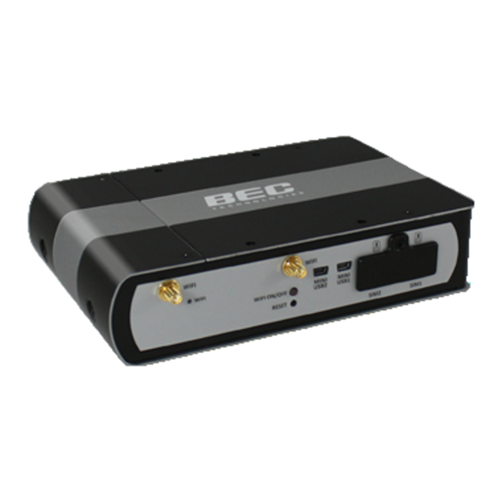
Page 12: Device Description
Device Description Index Item Description WiFi antenna Screw the supplied WiFi antennas onto the antenna connectors The single-colour LED behaves as follows: WiFi/WPS LED Green Wireless connection established Green blinking Data being transmitted / received By controlling the pressing time, users can achieve two different effects: WiFi On/Off (1) WiFi On/Off: Press &... - Page 13 Index Item Description Screw the supplied 4G LTE antennas onto the antenna connectors for 4G LTE module 4G LTE 1 antenna Screw the supplied 4G LTE antennas onto the antenna connectors for 4G LTE module 4G LTE 2 antenna GPS antenna Screw the supplied GPS antenna onto the antenna connectors.
- Page 14 Index Item Description The Power dual-colour LED behaves as shown below. Power LED Green System is up and ready Boot failure The Internet dual-colar LED behaves as shown below. Green IP connected and traffic is passing through the device. Internet LED IP request failed.
-
Page 15: The Detail Instruction In Reset Button
The detail instruction in Reset Button Recovery procedures for non-working routers (e.g. after a failed firmware upgrade flash): Power on the router, once the Power LED lit red, please press this reset button using the end of paper clip or other small pointed object immediately. The router’s emergency-reflash web interface will then be accessible via http://192.168.1.1 where you... -
Page 16: Cabling
Cabling One of the most common causes of problems is bad cabling. Make sure that all connected devices are turned on. On the front panel of the product is a bank of LEDs. Verify that the LAN Link and LEDs are lit. -
Page 17: Chapter 3: Basic Installation
Chapter 3: Basic Installation The router can be configured with your web browser. A web browser is included as a standard application in the following operating systems: Windows XP / Vista / 7 / 8, Linux, Mac OS, etc. The product provides an easy and user-friendly interface for configuration. -
Page 18: Network Configuration - Ipv4
Network Configuration – IPv4 Configuring PC in Windows 7/8 (IPv4) Go to Start. Click on Control Panel. Then click on Network and Internet. When the Network and Sharing Center window pops up, select and click on Change adapter settings on the left window panel. - Page 19 Select Internet Protocol Version 4 (TCP/IPv4) then click Properties. In the TCP/IPv4 properties window, select the Obtain an IP address automatically Obtain Server address automatically radio buttons. Then click OK to exit the setting. Click OK again in the Local Area Connection Properties window to apply the new configuration.
-
Page 20: Configuring Pc In Windows Vista (Ipv4)
Configuring PC in Windows Vista (IPv4) Go to Start. Click on Network. Then click on Network and Sharing Center at the top bar. When the Network and Sharing Center window pops up, select and click Manage network connections on the left window pane. - Page 21 Select Internet Protocol Version 4 (TCP/IPv4) then click Properties. In the TCP/IPv4 properties window, select the Obtain an IP address automatically and Obtain DNS Server address automatically radio buttons. Then click OK to exit the setting. Click OK again in the Local Area Connection Properties window to apply the new configuration.
-
Page 22: Configuring Pc In Windows Xp (Ipv4)
Configuring PC in Windows XP (IPv4) 1. Go to Start. Click on Control Panel. 2. Then click on Network and Internet. 3. In the Local Area Connection Status window, click Properties. 4. Select Internet Protocol (TCP/IP) and click Properties. 5. Select the Obtain an IP address automatically and the Obtain DNS server address automatically radio buttons. -
Page 23: Network Configuration - Ipv6
Network Configuration – IPv6 Configuring PC in Windows 7/8 (IPv6) Go to Start. Click on Control Panel. Then click on Network and Internet. When the Network and Sharing Center window pops up, select and click on Change adapter settings on the left window panel. - Page 24 Select Internet Protocol Version 6 (TCP/IPv6) then click Properties. In the TCP/IPv6 properties window, select the Obtain an IPv6 address automatically Obtain Server address automatically radio buttons. Then click OK to exit the setting. Click OK again in the Local Area Connection Properties window to apply the new configuration.
-
Page 25: Configuring Pc In Windows Vista (Ipv6)
Configuring PC in Windows Vista (IPv6) Go to Start. Click on Network. Then click on Network and Sharing Center at the top bar. When the Network and Sharing Center window pops up, select and click Manage network connections on the left window pane. - Page 26 Select Internet Protocol Version 6 (TCP/IPv6) then click Properties. In the TCP/IPv6 properties window, select the Obtain an IP address automatically and Obtain DNS Server address automatically radio buttons. Then click OK to exit the setting. Click OK again in the Local Area Connection Properties window to apply the new configuration.
-
Page 27: Configuring Pc In Windows Xp (Ipv6)
Configuring PC in Windows XP (IPv6) IPv6 is supported by Windows XP, but you need to install it first. Please follow the steps to install IPv6: 1. On the Desktop, Click Start > Run, type cmd, then press Enter key in the keyboard, the following screen appears. -
Page 28: Default Settings
Default Settings Before configuring the router, you need to know the following default settings. Web Interface: (Username and Password) Username: admin Password: admin The default username and password are “admin” and “admin” respectively. If you ever forget the username/password to login to the router, you may press the RESET button up to 6 seconds then release it to restore the factory default settings. -
Page 29: Information From Your Isp
Information from Your ISP Before configuring this device, you have to check with your ISP (Internet Service Provider) what kind of service is provided such as 4G LTE or EWAN ((Dynamic IP address, Static IP address, PPPoE, Bridge Mode). -
Page 30: Chapter 4: Device Configuration
Chapter 4: Device Configuration Login to your Device Open your web browser, enter the IP address of your router, which by default is 192.168.1.254, and click “Go”, a user name and password window prompt appears. The default username and password is “admin” and “admin” respectively for the Administrator. Congratulations! You have successfully logged on to your MX-1000 ! - Page 31 Once you have logged on to your MX-1000 via your web browser, you can begin to set it up according to your requirements. On the configuration homepage, the left navigation pane links you directly to the setup page, which includes: Status(Device Info, System Log, 4G LTE Status, GPS Status, Hardware Monitor, Statistics, DHCP Table, Disk Status, IPSec Status, PPTP Status, L2TP Status, GRE Status) Quick Start (Wizard Setup)
-
Page 32: Status
Status In this section, you can check the router working status, including Device Info, System Log, 4G LTE Status, GPS Status, Hardware Monitor, Statistics, DHCP Table, Disk Status, IPSec Status, PPTP Status, L2TP Status, GRE Status. -
Page 33: Device Info
Device Info It contains basic information of the device. Device Information Model Name: Show model name of the router Firmware Version: This is the Firmware version MAC Address: This is the MAC Address Date Time: The current date and time. System Up Time: The duration since system is up. - Page 34 DHCP Server: LAN port DHCP information. Wireless Mode: The wireless mode in use. SSID: The SSID. Channel: The current channel. Security: The wireless security setting, authentication type.
-
Page 35: System Log
System Log In system log, you can check the operations status and any glitches to the router. Refresh: Press this button to refresh the statistics. -
Page 36: 3G/4G-Lte Status
3G/4G-LTE Status This page contains 3G/4G-LTE connection information. Status: The current status of the 4G LTE connection. Signal Strength: The signal strength bar and dBm value indicates the current 4G LTE signal strength. The front panel 4G LTE Signal Strength LED indicates the signal strength as well. Signal Information: Shows important LTE signal parameters such as RSRP (Reference Signal Receiving Power), RSRQ (Reference Signal Receiving Quality), SINR (Signal to Interference plus Noise Ratio). -
Page 37: Gps Status
GPS Status In GPS status, you can check the UTC time, position of the router. -
Page 38: Hardware Monitor
Hardware Monitor In hardware monitor, you can check the voltage, current and temperature of system. -
Page 39: Statistics
Statistics 4G LTE Interface: List all available network interfaces in the router. You are currently checking on the physical status of 3G/4G-LTE interface. Transmit Frames of Current Connection: This field displays the total number of 4G LTE frames transmitted until the latest second for the current connection. Transmit Bytes of Current Connection: This field shows the total bytes transmitted till the latest second for the current connection for the current connection. - Page 40 EWAN Interface: List all available network interfaces in the router. You are currently checking on the physical status of the EWAN port. Transmit Frames: This field displays the total number of frames transmitted until the latest second. Transmit Multicast Frames: This field displays the total number of multicast frames transmitted till the latest second.
- Page 41 Ethernet Interface: List all available network interfaces in the router. You are currently checking on the physical status of the Ethernet port. Transmit Frames: This field displays the number of frames transmitted until the latest second. Transmit Multicast Frames: This field displays the number of multicast frames transmitted until the latest second.
- Page 42 Wireless Interface: List all available network interfaces in the router. You are currently checking on the physical status of the Wireless. Transmit Frames: This field displays the number of frames transmitted until the latest second. Transmit Error Frames: This field displays the number of error frames transmitted until the latest second.
-
Page 43: Dhcp Table
DHCP Table DHCP table displays the devices connected to the router with clear information. Index: The index identifying the connected devices. Host Name: Show the hostname of the PC. IP Address: The IP allocated to the device. MAC Address: The MAC of the connected device. Expire Time: The total remaining interval since the IP assignment to the PC. -
Page 44: Disk Status
Disk Status Partition: Display the USB storage partition. Disk Space (KB): Display the total storage space of the NAS in Kbytes unit. Free Space (KB): Display the available space in Kbytes unit. -
Page 45: Ipsec Status
IPSec Status Index: The IPSec tunnel index number. Action: Connect or Drop the connection. Connection Name: User-defined IPSes VPN connection name. Active: Show if the tunnel is active for connection. Connection State: Show the IPSec phase 1 and phase 2 connecting status. Statistics: Display the upstream/downstream traffic per session in KB. -
Page 46: Pptp Status
PPTP Status PPTP Server Index: The PPTP server tunnel index number. Connection Name: Show user-defined PPTP VPN connection name. Active: Show if the tunnel is active for connection. Connection State: Show the connecting status. Connection Type: Remote Access or LAN to LAN. Assigned IP Address: Show the IP assigned to the client by PPTP Server. -
Page 47: L2Tp Status
L2TP Status Index: The L2TP tunnel index number. Connection Name: Display the user-defined L2TP connection name. Active: Show if the tunnel is active for connection. Connection State: Show the connecting status. Connection Mode: The L2TP mode is dialin or dialout. Connection Type: Remote Access or LAN to LAN. -
Page 48: Gre Status
GRE Status Index: The GRE tunnel index number. Connection Name: Display the user-defined GRE connection name. Active: Show if the tunnel is active for connection. Connection State: Show the connecting status. Remote Gateway IP: The IP of the remote GRE gateway. Remote Network: Display the remote network. -
Page 49: Quick Start
Quick Start This is a useful and easy utility to help you to setup the router quickly and to connect to your ISP (Internet Service Provider) with only a few steps. It will guide you step by step to setup password, time zone, wireless and WAN settings of your device. - Page 50 Step 4 – ISP Connection Type Set up your Internet connection. 4.1 Select an appropriate WAN connection protocol then click NEXT to continue. Input all relevant 3G/4G-LTE parameters from your ISP. 4.2 If selected EWAN If selected PPPoE, please enter PPPoE account information provided by your ISP. Click NEXT to continue.
- Page 51 Step 5 – Quick Start Completed The Setup Wizard has completed. Click on BACK to modify changes or mistakes. Click NEXT to save the current settings. Step 6 – Quick Start Completed...
-
Page 52: Configuration
Configuration Click to access and configure the available features in the following: Interface Setup, Dual WAN, Advanced Setup, VPN, Access Management, and Maintenance. These functions are described in the following sections. -
Page 53: Interface Setup
Interface Setup Here are the features under Interface Setup: Internet, LAN, Wireless and Wireless MAC Filter. -
Page 54: Internet
Internet 4G LTE Status: Choose Activated to enable the 3G/4G-LTE connection. Usage Allowance: to control 4G LTE flow, click it to further configure about 4G LTE flow control, refer to the following Usage Allowance for more information. Network Mode: There are some options of service standards: “Automatic”, “UMTS 3G only”, “GSM 2G Only”, “UMTS 3G Preferred”, “GSM 2G Preferred”, “GSM and UMTS Only”, “LTE Only”, “GSM, UMTS, LTE”. - Page 55 Keep Alive IP: Enter the IP address whic is used for “ping”, and router will ping the IP to find whether the connection is on or not, if not, router will recover the connection. Default Route: Select Yes to use this interface as default route interface. NAT: Select this option to Disabled/Enable the NAT (Network Address Translation) function.
- Page 56 EWAN ...
- Page 57 Status: Select whether to enable the service. IPv4/IPv6 IP Version: Choose IPv4, IPv4/IPv6, IPv6 based on your environment. If you don’t know which one to choose from, please choose IPv4/IPv6 instead. ISP Connection Type: ISP: Select the encapsulation type your ISP uses. ...
- Page 58 device acts as a NAT router; while if you dial up with the account within your PC, the device will then work as a bridge forwarding the PPPoE information to the PPPoE server and send the response to your PC, thus your PC gets a public WAN IP working in the internet. Connection Setting Connection: Always On: Click on Always On to establish a PPPoE session during start up and to...
- Page 59 Dynamic Route: RIP Version: (Routing Information protocol) Select this option to specify the RIP version, including RIP-1, RIP-2. RIP Direction: Select this option to specify the RIP direction. None is for disabling the RIP function. Both means the router will periodically send routing information and accept routing information then incorporate into routing table.
-
Page 60: Lan
A Local Area Network (LAN) is a shared communication system to which many computers are attached and is limited to the immediate area, usually the same building or floor of a building. - Page 61 IPv4 Parameters IP Address: Enter the IP address of Router in dotted decimal notation, for example, 192.168.1.254 (factory default). IP Subnet Mask: The default is 255.255.255.0. User can change it to other such as 255.255.255.128. Alias IP Address: This is for local networks virtual IP interface. Specify an IP address on this virtual interface.
- Page 62 IP Pool Count: This field specifies the count of the IP address pool. Lease Time: The current lease time of client. DNS Relay Select Automatically obtained or Manually set (if selected. Please set the exactly information). Primary DNS Server: Enter the IP addresses of the DNS servers. The DNS servers are passed to the DHCP clients along with the IP address and the subnet mask.
- Page 63 anything on the client. Stateful configuration, for example using DHCPv6 (which resembles its counterpart DHCP in IPv4.) In the stateful auto configuration model, hosts obtain interface addresses and/or configuration information and parameters from a DHCPv6 server. The Server maintains a database that keeps track of which addresses have been assigned to which hosts.
-
Page 64: Wireless
Wireless This section introduces the wireless LAN and some basic configurations. Wireless LANs can be as complex as a number of computers with wireless LAN cards communicating through access points which bridge network traffic to the wired LAN. - Page 65 Access Point Settings Access Point: Default setting is set to Activated. If you want to close the wireless interface, select Deactivated. AP MAC Address: The MAC address of wireless AP. Wireless Mode: The default setting is 802.11b+g+n (Mixed mode). If you do not know or have both 11g and 11b devices in your network, then keep the default in mixed mode.
- Page 66 11n Settings Channel Bandwidth: Select either 20 MHz or 20/40 MHz for the channel bandwidth. The wider the Channel bandwidth the better the performance will be. Guard Interval: Select either 400nsec or 800nsec for the guard interval. The guard interval is here to ensure that data transmission do not interfere with each other.
- Page 67 supports 2 types of configuration methods which are commonly known among consumers: Method & Method. Use WPS: Enable this feature by choosing the ”YES” radiobutton. WPS State: Display whether the WPS is configured or unconfigured. WPS Mode: Select the mode which to start WPS, choose between PIN Code and PBC (Push Button). Selecting Pin Code mode will require you to know the enrollee PIN code.
- Page 68 WEP-64Bits/ WEP-128Bits, the following prompt box will appear to notice you. WPA-PSK, WPA2-PSK, Mixed WPA2/WPA-PSK WPA Algorithms: TKIP (Temporal Key Integrity Protocol) or AES (Advanced Encryption System) utilizes a stronger encryption method and incorporates Message Integrity Code (MIC) to provide protection against hackers.
- Page 69 Wi-Fi Protected Setup (WPS) Example I: PIN Method: Configure AP as Registrar 1. Jot down the client’s Pin (e.g. 04640776). 2. Enter the Enrollee (Client) PIN code and then press Start WPS. 3. Launch the wireless client’s WPS utility (e.g. Ralink Utility). Set the Config Mode as Enrollee, press the WPS button on the top bar, select the AP (e.g.
- Page 70 4. The client’s SSID and security setting will now be configured to match the SSID and security setting of the registrar (router).
- Page 71 Wi-Fi Protected Setup (WPS) Example II: PIN Method: Configure AP as Enrollee 1. Jot down the WPS PIN (e.g. 70963205). Press Start WPS. 2. Launch the wireless client’s WPS utility (e.g. Ralink Utility). Set the Config Mode as Registrar. Enter the PIN number in the PIN Code column then choose the correct AP (e.g.
- Page 72 4. Now to make sure that the setup is correctly done, cross check to see if the SSID and the security setting of the registrar setting match with the parameters found on both Wireless Configuration and Wireless Security Configuration page.
- Page 73 Wi-Fi Protected Setup (WPS) Example III: PBC Method: 1. Press the PBC radio button, Then Start WPS. 2. Launch the wireless client’s WPS Utility (e.g. Ralink Utility). Set the Config Mode as Enrollee. Then press the WPS button and choose the correct AP (e.g. Billion_AP) from the WPS AP List section before pressing the PBC button to run the scan.
-
Page 74: Wireless Mac Filter
Wireless MAC Filter The MAC filter screen allows you to configure the router to give exclusive access to up to 8 devices (Allow Association) or exclude up to 8 devices from accessing the router (Deny Association). Every Ethernet device has a unique MAC (Media Access Control) address. The MAC address is assigned at the factory and consists of six pairs of hexadecimal characters, for example, 00:AA:BB:00:00:02. -
Page 75: Dual Wan
Dual WAN Dual WAN is specially designed to offer users failover/fallback. Auto failover/failback is to ensure an always-on internet connection. Users can set a WAN1 (main WAN) and WAN 2 (backup WAN), and when WAN1 fails, it will switch to WAN2, and when WAN1 restores, it will switch to WAN1 again. - Page 76 Failover & Failback WAN Port Service Detection Policy WAN1: Select “4G LTE 1”, “4G LTE 2” or “EWAN” for WAN1 (The main WAN). WAN2: Select the “4G LTE 2” or “EWAN” for WAN2 as backup port if you select “4G LTE 1” as WAN1. Keep Backup Interface Connected: Select if to keep backup WAN interface connected.
- Page 77 Failover & Priority WAN Port Service Detection Policy WAN1: Select “4G LTE 1”, “4G LTE 2” or “EWAN” for WAN1 (The main WAN). WAN2: Select the “4G LTE 2” or “EWAN” for WAN2 as backup port if you select “4G LTE 1” as WAN1. Connectivity Decision: Set how many times of probing failure to switch to backup port.
- Page 78 Load Balance WAN Port Service Detection Policy WAN1: Select “4G LTE 1”, “4G LTE 2” or “EWAN” for WAN1 (The main WAN). WAN2: Select the “4G LTE 2” or “EWAN” for WAN2 as backup port if you select “4G LTE 1” as WAN1. Service Detection: Select if to keep detecte WAN interface connected.
-
Page 79: Outbound Load Balance
Outbound Load Balance The connections are distributed over WAN1 and WAN2 so that it can utilize bandwidth of both WAN ports. With Outbound load balance, traffic may be routed to a faster link when one of the WAN is slower or congested so that user gains better throughput and less delay. User can distribute outbound traffic based on Session Mechanism or IP Hash Mechanism. -
Page 80: Protocol Binding
Protocol Binding Protocol Binding lets you direct specific traffic to go out from a specific WAN port. Policies determine how specific types of internet traffic are routed, for example, traffic from a particular IP(es) granted access to only one WAN port rather than using both of the WAN ports as with load balancing. Rule Index: The index marking the rule. -
Page 81: Advanced Setup
Advanced Setup Advanced Step provides advanced features including Firewall, Routing, NAT, Static DNS, Time Schedule, Mail Alert and Remote System Log for advanced users. -
Page 82: Firewall
Firewall Your router includes a firewall for helping to prevent attacks from hackers. In addition to this, when using NAT (Network Address Translation) the router acts as a “natural” Internet firewall, since all PCs on your LAN use private IP addresses that cannot be directly accessed from the Internet. Firewall: To automatically detect and block Denial of Service (DoS) attacks, such as Ping of Death, SYN Flood, Port Scan and Land Attack. -
Page 83: Routing
Routing This is static route feature. You are equipped with the capability to control the routing of all the traffic across your network. With each routing rule created, user can specifically assign the destination where the traffic will be routed to. Index: Item number Destination IP Address: IP address of the destination network Subnet Mask: The subnet mask of destination network. -
Page 84: Nat
The NAT (Network Address Translation) feature transforms a private IP into a public IP, allowing multiple users to access the internet through a single IP account, sharing the single IP address. NAT break the originally envisioned model of IP end-to-end connectivity across the internet so NAT can cause problems where IPSec/ PPTP encryption is applied or some application layer protocols such as SIP phones are located behind a NAT. - Page 85 NOTE: This feature disables automatically if WAN connection is in BRIDGE mode. The DMZ Host is a local computer exposed to the Internet. When setting a particular internal IP address as the DMZ Host, all incoming packets will be checked by the Firewall and NAT algorithms then passed to the DMZ host, when a packet received does not use a port number used by any other Virtual Server entries.
- Page 86 Virtual Server NOTE: This feature disables automatically if WAN connection is in BRIDGE mode. The device can be configured as a virtual server so that remote users accessing services such as Web or FTP services via the public (WAN) IP address can be automatically redirected to local servers in the LAN network.
- Page 87 Examples of well-known and registered port numbers are shown below. For further information, please see IANA’s website at http://www.iana.org/assignments/port-numbers Well-known and Registered Ports Port Number Protocol Description FTP Control TCP & UDP SSH Remote Login Protocol Telnet SMTP (Simple Mail Transfer Protocol) TCP &...
- Page 88 Example : How to setup Port Forwarding for port 21 (FTP server) If you have a FTP server in your LAN network and want others to access it through WAN. Step 1: Assign a static IP to your local computer that is hosting the FTP server. Step 2: Login to the Gateway and go to Configuration / Advanced Setup / NAT / Virtual Server.
-
Page 89: Static Dns
Static DNS The Domain Name System (DNS) is a hierarchical naming system built on a distributed database for computers, services, or any resource connected to the Internet or a private network associates various information with domain names assigned to each of the participating entities. Most importantly, it translates domain names meaningful to humans into the numerical identifiers associated with networking equipment for the purpose of locating and addressing these devices worldwide. -
Page 90: Time Schedule
Time Schedule The Time Schedule supports up to 16 timeslots which helps you to manage your Internet connection. In each time profile, you may schedule specific day(s) i.e. Monday through Sunday to restrict or allowing the usage of the Internet by users or applications. This Time Schedule correlates closely with router’s time, since router does not have a real time clock on board;... - Page 91 For example, user can add a timeslot named “TimeSlot1” which features a period from 9:00 of Saturday to 18:00 of Sunday. Another TimeSlot2 spanning from 09:00 to 18:00 of Wednesday...
-
Page 92: Mail Alert
Mail Alert Mail alert is designed to keep system administrator or other relevant personnel alerted of any unexpected events that might have occurred to the network computers or server for monitoring efficiency. With this alert system, appropriate solutions may be tackled to fix problems that may have arisen so that the server can be properly maintained. -
Page 93: Remote System Log
Remote System Log Remote System Log is designed to keep remote administrators informed of the system-operating information. Administrator can set up a remote system log server for receiving and monitoring the system information by enabling remote system log feature on the router. Remote System Log: Select whether to activate “Remote System Log”. -
Page 94: Vpn
A Virtual Private Network (VPN) is a private network that interconnects remote (and often geographically separate) networks through primarily public communication infrastructures such as the Internet. VPNs provide security through tunneling protocols and security procedures such as encryption. For example, a VPN could be used to securely connect the branch offices of an organization to a head office network through the public Internet. -
Page 95: Ipsec
IPSec Internet Protocol Security (IPSec) is a protocol suite for securing Internet Protocol (IP) communications by authenticating and encrypting each IP packet of a communication session. IPsec also includes protocols for establishing mutual authentication between agents at the beginning of the session and negotiation of cryptographic keys to be used during the session. - Page 96 IPSec Connection Setting Connection Name: A given name for the connection (e.g. “connection to office”). Active: Select Yes to activate the tunnel. Interface: Select the set used interface for the IPSec connection, when you select 3G/4G-LTE interface, the IPSec tunnel would via this interface to connect to the remote peer. Remote Gateway IP: The WAN IP address of the remote VPN gateway that is to be connected, establishing a VPN tunnel.
- Page 97 Single IP: The IP address of the local host, for establishing an IPSec connection between a security gateway and a host (network-to-host). If the remote peer is a host, select Single Address. Subnet: The subnet of the local network, for establishing an IPSec tunnel between a pair of security gateways (network-to-network), If the remote peer is a network, select Subnet.
- Page 98 IPSec Phase 2(IPSec) IPSec Proposal: Select the IPSec security method. There are two methods of verifying the authentication information, AH(Authentication Header) and ESP(Encapsulating Security Payload). Use ESP for greater security so that data will be encrypted and the data origin be authenticated but using AH data origin will only be authenticated but not encrypted.
- Page 99 address. DPD: Dead peer detection (DPD) is a keeping alive mechanism that enables the router to be detected lively when the connection between the router and a remote IPSec peer has lost. Please be noted, it must be enabled on the both sites. PING to the IP: It is able to IP Ping the remote PC with the specified IP address and alert when the connection fails.
- Page 100 Examples: How to establish an IPSec Tunnel 1. LAN-to-LAN connection Two MX-1000 want to setup a secure IPSec VPN tunnel Note: The IPSec Settings shall be consistent between the two routers.
- Page 101 Head Office Side: Item Description Connection Name H-to-B Name for IPSec tunnel Remote Secure Gateway 69.121.1.30 IP address of the Branch office gateway Access Netork Local Access Range Subnet Head Office network Local Netwrok IP Address 192.168.1.0 Local Netwrok Netmask 255.255.255.0 Remote Access Range Subnet...
- Page 102 Branch Office Side: Item Description Connection Name B-to-H Name for IPSec tunnel Remote Secure Gateway 69.121.1.3 IP address of the Branch office gateway Access Netork Local Access Range Subnet Head Office network Local Netwrok IP Address 192.168.0.0 Local Netwrok Netmask 255.255.255.0 Remote Access Range Subnet...
- Page 103 2. Host to LAN Router servers as VPN server, and host should install the IPSec client to connect to head office through IPSec VPN.
- Page 104 Head Office Side: Item Description Connection Name H-to-H Name for IPSec tunnel Remote Secure Gateway 69.121.1.30 IP address of the Branch office gateway Access Netork Local Access Range Subnet Head Office network Local Netwrok IP Address 192.168.1.0 Local Netwrok Netmask 255.255.255.0 Remote Access Range Signal IP...
-
Page 105: Pptp Server
PPTP Server The Point-to-Point Tunneling Protocol (PPTP) is a Layer2 tunneling protocol for implementing virtual private networks through IP network. In the Microsoft implementation, the tunneled PPP traffic can be authenticated with PAP, CHAP, and Microsoft CHAP V1/V2 . The PPP payload is encrypted using Microsoft Point-to-Point Encryption (MPPE) when using MSCHAPv1/v2. - Page 106 Click Save button to save your changes.
-
Page 107: Pptp Client
PPTP Client PPTP client can help you dial the PPTP server to establish PPTP tunnel over Internet. A total of 4 sessions can be created for PPTP client. Rule Index: 4 rules can be added, 1-4 digit to mark each rule. Connection Name: User-defined name for the PPTP connection. - Page 108 Example: PPTP Dial-in Remote Access connection...
- Page 109 Configuring PPTP Server in the Office The input IP address 192.168.1.2 will be assigned to the remote worker. Please make sure this IP is not used in the Office LAN. Item Description Connection Name HS-RA Give a name of L2TP conneciton Authentication Type MPPE 128bit Authentication type...
- Page 110 Example: PPTP LAN to LAN connection The branch office establishes a PPTP VPN tunnel with head office to connect two private networks over the Internet. The routers are installed in the head office and branch offices accordingly. Note: Both office LAN networks must be in different subnets with the LAN-LAN application.
- Page 111 Configuring PPTP Server in the Head office The IP address 192.168.1.2 will be assigned to the router located in the branch office. Please make sure this IP is not used in the head office LAN. Item Description Connection Name HS-LL Give a name of PPTP conneciton Authentication Type MPPE 128bit...
- Page 112 Configuring PPTP Client in the Branch office The IP address 69.1.121.33 is the Public IP address of the router located in head office. Item Description Connection Name BC-LL Give a name of PPTP conneciton Authentication Type MPPE 128bit Authentication type Username test Dial in authenticate user name...
-
Page 113: L2Tp
L2TP L2TP, Layer 2 Tunneling Protocol is a tunneling protocol used to support virtual private networks (VPNs). It does not provide any encryption or confidentiality by itself; it relies on an encryption protocol that it passes within the tunnel to provide. Note: 4 sessions for dial-in connections and 4 sessions for dial-out connections Rule Index: The Index to mark the session. - Page 114 server. The IP should be in the same subnet as local LAN, and should not be occupied. Connection Mode: Choose Dial Out if you want your router to operate as a client (connecting to a remote L2TP Server, e.g, your office server). Server IP Address: Enter the IP address of your VPN Server.
- Page 115 Active as Default Route: Enabled to let the tunnel to be the default route for traffic, under this circumstance, all packets will be forwarded to this tunnel and routed to the next hop.
- Page 116 Examples: 1. Configuring a L2TP VPN - Remote Access Dial-in Connection A remote worker establishes a L2TP VPN connection with the head office using Microsoft's VPN Adapter (included with Windows XP/2000/ME, etc.). The router is installed in the head office, connected to a couple of PCs and Servers.
- Page 117 Configuring L2TP VPN Dial-in in the Office The input IP address 192.168.1.200 will be assigned to the remote worker. Please make sure this IP is not used in the Office LAN. Item Description Connection Name HS-RA Give a name of L2TP conneciton Connection Mode Dial in Operate as L2TP server...
- Page 118 2. Configuring a Remote Access L2TP VPN Dial-out Connection A company’s office establishes a L2TP VPN connection with a file server located at a separate location. The router is installed in the office, connected to a couple of PCs and Servers.
- Page 119 Configuring L2TP VPN Dial-out in the Office Item Description Connection Name HC-RA Give a name of L2TP conneciton Connection Mode Dial out Operate as L2TP client Server IP 69.121.1.33 Dialed server IP Authentication Type Chap/Pap Authentication type Username test Dial out authenticate user name Passwrod test Dial out authenticate user password...
- Page 120 Example: Configuring L2TP LAN-to-LAN VPN Connection The branch office establishes a L2TP VPN tunnel with head office to connect two private networks over the Internet. The routers are installed in the head office and branch office accordingly. Note: Both office LAN networks must be in different subnets with the LAN-LAN application.
- Page 121 Configuring L2TP VPN Dial-in in the Head office The IP address 192.168.1.200 will be assigned to the router located in the branch office. Please make sure this IP is not used in the head office LAN. Item Description Connection Name HS-LL Give a name of L2TP conneciton Connection Mode...
- Page 122 Configuring L2TP VPN Dial-out in the Branch office The IP address 69.1.121.33 is the Public IP address of the router located in head office. Item Description Connection Name BC-LL Give a name of L2TP conneciton Connection Mode Dial out Operate as L2TP client Server IP 69.121.1.33 Dialed server IP...
-
Page 123: Gre Tunnel
GRE Tunnel Generic Routing Encapsulation (GRE) is a tunneling protocol that can encapsulate a wide variety of network layer protocol packets inside virtual point-to-point links over an IP network. Note: up to 8 tunnels can be added. Rule Index: 8 GRE rules can be added, 1-8 digit to mark each rule. Connection Name: User-defined name for the connection. - Page 124 MTU: Maximum Transmission Unit. Active as Default Route: Select if to set the GRE tunnel as the default route.
-
Page 125: Access Management
Access Management Access Management equipments the users with the ability of maintaining the access management, including Device Management, SNMP, Universal Plug & Play, Dynamic DNS, Access Control, Packet Filter, CWMP(TR-069), Parental Control, and SAMBA & FTP Server. -
Page 126: Device Management
Device Management Device management offers users a way to change the embedded web server accessing port, default 80. User can change the http port to 8080 or something else here. -
Page 127: Snmp
SNMP Simple Network Management Protocol (SNMP) is a protocol used for exchanging management information between network devices. SNMP is a member of the TCP/IP protocol suite. MX-1000 serves as a SNMP agent which allows a manager station to manage and monitor the router through the network. -
Page 128: Universal Plug & Play
Universal Plug & Play UPnP offers peer-to-peer network connectivity for PCs and other network devices, along with control and data transfer between devices. UPnP offers many advantages for users running NAT routers through UPnP NAT Traversal, and on supported systems makes tasks such as port forwarding much easier by letting the application control the required settings, removing the need for the user to control advanced configuration of their device. -
Page 129: Dynamic Dns
Dynamic DNS The Dynamic DNS function allows you to alias a dynamic IP address to a static hostname, allowing users whose ISP does not assign them a static IP address to use a domain name. This is especially useful for hosting servers via your internet connection, so that anyone wishing to connect to you may use your domain name, rather than having to use your dynamic IP address, which changes from time to time. - Page 130 Example: How to register a DDNS account Note first users have to go to the Dynamic DNS registration service provider to register an account. User test1 register a Dynamic Domain Names in DDNS provider http://www.dyndns.org/ DDNS: www.hometest.com using username/password test/test...
-
Page 131: Access Control
Access Control Access Control Listing allows you to determine which services/protocols can access MX-1000 interface from which computers. It is a management tool aimed to allow IPs (set in secure IP address) to access specified embedded applications (Web, etc, user can set) through some specified interface (LAN, WAN or both). - Page 132 By default, the “Access Control” has two default rules. Default Rule 1: (Index 1), a rule to allow only clients from LAN to have access to all embedded applications (Web, FTP, etc). Under this situation, clients from WAN cannot access the router even from Ping.
-
Page 133: Packet Filter
Packet Filter You can filter the packages by MAC address, IP address, Protocol, Port number and Application or URL. Packet Filter - IP & MAC Filter Packet Filter Filter Type: There are three types “IP & MAC Filter”, “Application Filter”, and “URL Filter” that user can select for this filter rule. - Page 134 Source IP Address: The source IP address of packets to be monitored. 0.0.0.0 means “Don’t care”. Source Subnet Mask: Enter the subnet mask of the source network. Source Port Number: The source port number of packets to be monitored. 0 means “Don’t care”. Destination IP Address: The destination IP address of packets to be monitored.
- Page 135 Packet Filter - Application Filter Application Filter: Select this option to Activated/Deactivated the Application filter. ICQ: Select this option to Allow/Deny ICQ. MSN: Select this option to Allow/Deny MSN. YMSG: Select this option to Allow/Deny Yahoo messenger. Real Audio/Video (RTSP): Select this option to Allow/Deny Real Audio/Video (RTSP).
- Page 136 Packet Filter - URL Filter URL Filter: Select Activated to enable URL Filter. URL Filter Rule Index: This is item number. Individual Active: To give control to the specific URL access individually, for example, you want to prohibit access to www.yahoo.com, please first press Activated in “URL Filter” field, and also Yes in “Individual Active”...
-
Page 137: Cwmp (Tr-069)
CWMP (TR-069) CWMP, short for CPE WAN Management Protocol, also called TR069 is a Broadband Forum technical specification entitled CPE WAN Management Protocol (CWMP). It defines an application layer protocol for remote management of end-user devices. It defines an application layer protocol for remote management of end-user devices. - Page 138 Periodic Inform Config Periodic Inform: Select Activated to authorize the router to send an Inform message to the ACS automatically. Interval(s): Specify the inform interval time (sec) which CPE used to periodically send inform message to automatically connect to ACS. When the inform interval time arrives, the CPE will send inform message to automatically connect to ACS.
-
Page 139: Parental Control
Parental Control Parental Control provides Web content filtering offering safer and more reliable web surfing for users. Please get an account and configure at the selected Provider “www.opendns.com” in advance. If activated, the Parental Control has the top priority as DNS when accessing internet. Host Name, Username and Password: Enter your registered domain name and your username and password at the provider website www.opendns.com. -
Page 140: Samba & Ftp Server
SAMBA & FTP Server Samba and FTP are served as network sharing. SAMBA Server: Activated to enable SAMBA sharing. Work Group: The same mechanism like in Microsoft work group, please set the Work Group name. NetBIOS Name: The sharing NetBIOS name. FTP Server: Activated to enable FTP sharing. - Page 141 Example: How to setup Samb 1. Go directly to Start > Run (enter \\192,168,1,254 (from LAN side), \\SambaSvr , but if you enter \\SambaSvr, please be sure your working PC is in the same workgroup as set in the samba server set above.) 2.
- Page 142 Example: How to setup FTP: 1. Access via FTP tools Take popular FTP tool of FlashFXP for example: 1) Open FlashFXP 2) Create ftp sites (LAN IP / WAN IP, 192.168.1.254, and set the account, port). 3) Connect to the ftp site. 2.
-
Page 143: Maintenance
Maintenance Maintenance equipments the users with the ability of maintaining the device as well as examining the connectivity of the WAN connections, including User Management, Time Zone, Firmware & Configuration, System Restart, and Diagnostic Tool. -
Page 144: User Management
User Management User Management controls the Router Web GUI permission, FTP/SAMBA access to the specific account. In factory setting, the default accounts are admin/admin and user/user. The default root account admin has been authorized to web access of router, Samba access, and FTP access. user/user is equipment with limited access (specified by advanced users with admin account) to router web, and FTP/SAMBA . - Page 145 Admin / Admin admin/admin is the root account provided by our router. User Setup Index: User account index, total is 8. User Name: Users can create account(s) to give it (them) access to SAMBA and FTP. New Password: Enter a new password for this user account. Confirmed Password: Re-enter the new password again;...
- Page 147 User / User and/or Adding additonal user accounts User Setup Index: User account index, total is 8. User Name: Users can create account(s) to give it (them) access to SAMBA and FTP. New Password: Type the password for the user account. Confirmed Password: Type password again for confirmation.
- Page 148 VoIP Setup, Access Management and Maintenance access. Enable to have access to Interface Setup, Advanced Setup and Access Management or disable to set the specifics yourself. Interface Setup: Enable to allowing access to Interface Setup with this account. Advanced Setup: Enable to allowing access to Advanced Setup with this account. VOIP Setup: Enable to allowing access to VoIP Setup with this account.
- Page 149 Web GUI shown when “user” account uses Guest account on Web GUI Permission...
-
Page 150: Time Zone
Time Zone The router does not have a real time clock on board; instead, it uses the Simple Network Time Protocol (SNTP) to get the current time from an SNTP server outside your network. Choose your local time zone. After a successful connection to the Internet, the router will retrieve the correct local time from the SNTP server you have specified. -
Page 151: Firmware & Configuration
Firmware & Configuration Firmware is the software that controls the hardware and provides all functionalities which are available in the GUI. This software may be improved and/or modified; your MX-1000 provides an easy way to update the code to take advantage of the changes. . To upgrade the firmware of MX-1000, you should download or copy the firmware to your local environment first. -
Page 152: System Restart
System Restart Click System Restart with option Current Settings to reboot your router. If you wish to restart the router using the factory default settings (for example, after a firmware upgrade or if you have saved an incorrect configuration), select Factory Default Settings to restore to factory default settings. -
Page 153: Auto Reboot
Auto Reboot Auto reboot offers flexible rebooting service (reboot with the current configuration) of router for users in line with scheduled timetable settings Enable to set the time schedule for rebooting. For example, the router is scheduled to reboot at 22:00 every single weekday, and to reboot at 9:00 on Saturday and Sunday. -
Page 154: Diagnostics Tool
Diagnostics Tool The Diagnostic Test page shows the test results for the connectivity of the physical layer and protocol layer for both LAN and WAN sides. 3G/4G-LTE: Click START to begin to diagnose the connection. EWAN: Click START to begin to diagnose the connection. -
Page 155: Chapter 5: Troubleshooting
Chapter 5: Troubleshooting If your MX-1000 is not functioning properly, you can refer to this chapter for simple troubleshooting before contacting your service provider support. This can save you time and effort but if symptoms persist, consult your service provider. Problems with the Router Problem Suggested Action... - Page 156 - The front LEDs display incorrectly Before starting recovery process, please configure - Still cannot access to the router the IP address of the PC as 192.168.1.100 and management interface after pressing the proceed with the following step-by-step guide. RESET button. 1.
-
Page 157: Appendix: Product Support & Contact
Appendix: Product Support & Contact If you come across any problems please contact the dealer from where you have purchased the product. Contact Billion WORLDWIDE http://www.billion.com MAC OS is a registered Trademark of Apple Computer, Inc. Windows 7/98, Windows NT, Windows 2000, Windows ME, Windows XP, and Windows Vista are registered... - Page 158 Federal Communication Commission Interference Statement This equipment has been tested and found to comply with the limits for a Class B digital device, pursuant to Part 15 of the FCC Rules. These limits are designed to provide reasonable protection against harmful interference in a residential installation. This equipment generates, uses, and can radiate radio frequency energy and, if not installed and used in accordance with the instructions, may cause harmful interference to radio communications.
Need help?
Do you have a question about the BEC MX-1000 and is the answer not in the manual?
Questions and answers