Table of Contents
Advertisement
Quick Links
Advertisement
Table of Contents

Related Manuals for Advantech ARK-1250L


Summary of Contents for Advantech ARK-1250L
- Page 1 User Manual ARK-1250L Fanless Embedded Box Computer...
- Page 2 This product contains a hard copy of the Chinese user manual for China CCC certifi- cation purposes. A PDF of the English user manual is available online. Please disre- gard the hard copy Chinese user manual if the product is not sold and/or installed in China. ARK-1250L User Manual...
- Page 3 The documentation and the software included with this product are copyrighted 2022 by Advantech Co., Ltd. All rights are reserved. Advantech Co., Ltd. reserves the right to make improvements in the products described in this manual at any time without notice.
- Page 4 Because of Advantech’s high quality-control standards and rigorous testing, most of our customers never need to use our repair service. If an Advantech product is defec- tive, it will be repaired or replaced at no charge during the warranty period. For out- of-warranty repairs, you will be billed according to the cost of replacement materials, service time and freight.
- Page 5 Les remarques fournissent des informations supplémentaires faculta- tives. Technical Support and Assistance Visit the Advantech web site at www.advantech.com/support where you can find the latest information about the product. Contact your distributor, sales representative, or Advantech's customer service center for technical support if you need additional assistance. Please have the following information ready before you call: –...
- Page 6 Packing List Before installation, check that the following items were included with the product: 1 x ARK-1250L unit 1 x XARK-ADP-90MDH 19V/90W adapter 1 x 4-pin connector to remote switch 1 x DIN-rail bracket 1 x Registration and 2-year warranty card ...
- Page 7 70 dB (A). DISCLAIMER: These instructions are provided according to IEC 704-1 specifi- cations. Advantech disclaims all responsibility for the accuracy of any state- ments contained herein. The product is intended to be supplied by an UL listed power Supply suitable for use at minimum Tma 60 °C which output is rated: 12-24Vdc, 7.5-3.75A min.
- Page 8 Jetez les piles usagées conformément aux instructions du fabricant. Débranchez toujours complètement le cordon d'alimentation de votre chassis lorsque vous utilisez du matériel. Ne faites pas de connexion quand l'appareil magés par des surtensions soudaines. ARK-1250L User Manual viii...
- Page 9 1: 1982 n'est pas supérieur à 70 dB (A). AVERTISSEMENT: Cet ensemble d'instructions est donné conformément à la norme CEI 704-1. Advantech décline toute responsabilité quant à l'exactitude des déclarations contenues dans ce. Le produit est destiné à être alimenté par une alimentation électrique réper- toriée UL adaptée à...
- Page 10 ARK-1250L User Manual...
-
Page 11: Table Of Contents
Figure 2.6 USB 2.0 Connector........... 13 Table 2.8: USB 2.0 PIN Definition ..........13 2.4.6 Audio Connector ................. 14 Figure 2.7 Audio Connector............14 2.4.7 COM Connector ................14 Figure 2.8 COM Connector............14 Table 2.9: COM Connector PIN Definitions....... 14 ARK-1250L User Manual... - Page 12 Main Setup.................. 28 3.2.2 Advanced BIOS Setup..............29 3.2.3 Chipset..................51 3.2.4 Security..................63 3.2.5 Boot .................... 65 3.2.6 Save & Exit ................. 66 Appendix A Watchdog Timer Sample Code ..67 EC Watchdog Timer sample code ............68 ARK-1250L User Manual...
-
Page 13: Chapter 1 General Introduction
Chapter General Introduction This chapter details background information on the ARK-1250L series. -
Page 14: Introduction
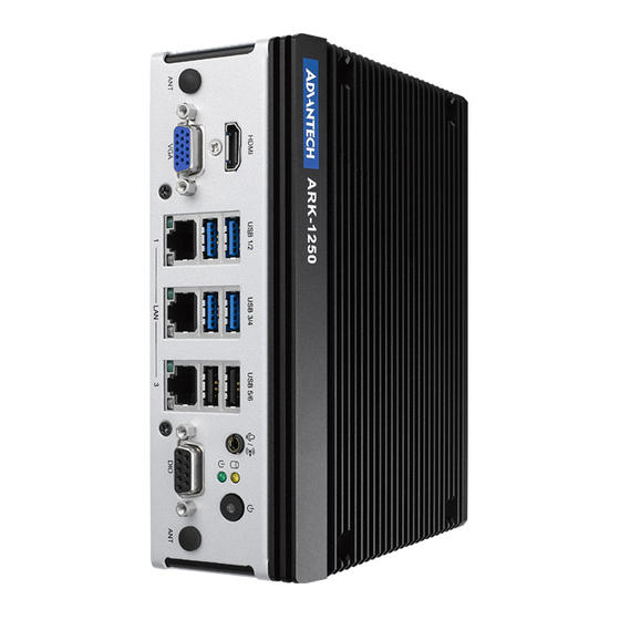
10/100/1000 Mbps LAN port, as well as 1 x Mic In/Line Out, 1 x HDMI, and 1 x VGA. ARK-1250L also features 1 x full-sized mini PCIE, 1 x M.2 2230 E key, 1 x M.2 2280 B key, and a 2.5” SSD. It is suitable for installation in environments with limited space. -
Page 15: Graphics
Power Adapter: AC to DC, 90W/120W adapter 1.2.12 Power Consumption Typical: 18W with Core i3-1115G4E, 19.8W with Core i5-1145G7E (OS idle mode) Max.: 30.6W with Core i3-1115G4E, 35.1W with Core i5-1145G7E (full loading) ARK-1250L User Manual... -
Page 16: Mechanical
Vibration during Operation: With SSD: 3 Grms, IEC60068-2-64, random, 5~500 Hz, and 1hr/axis Shock during Operation: With SSD: 30 G, IEC-60068-2-27, half sine, 11 ms duration EMC: CE/FCC Class B, CCC, and BSMI Safety: UL, CB, CCC, and BSMI ARK-1250L User Manual... -
Page 17: Mechanical Diagrams
Mechanical Diagrams ARK-1250L User Manual... -
Page 18: Optional Mos Modules For Idoor Expansion
GigaLAN Ethernet module, mPCIe, RJ45 2-Ch, PCIe I/F MOS-2220-Z1101E High-speed Serial COM module, 1-Ch, USB Interface Note! You need to order the AMO-I032 together with MOS modules mPCIe and M.2 E Key cannot be used when adding any MOS module due to mechanical interference ARK-1250L User Manual... -
Page 19: Chapter 2 H/W Installation
Chapter H/W Installation This chapter details instructions for installing the ARK-1250L series. Note: Hardware installation must be performed by skilled personnel... -
Page 20: Introduction
2.2.1 Jumper Description ARK-1250L can be configured to satisfy specific application requirements by setting jumpers. A jumper is a metal bridge used to close an electric circuit. It consists of two metal pins and a small metal clip (often protected by a plastic cover) that slides over the pins to connect them. -
Page 21: Jumper Location
2.2.3 Jumper Location Figure 2.1 Jumper Layout 2.2.4 Jumper Settings Table 2.2: J1: AT/ATX Mode Description ATX Mode (default) AT Mode Table 2.3: JCMOS1: Clear CMOS Description Normal operation (default) Clear CMOS ARK-1250L User Manual... - Page 22 ERP regulation. Table 2.5: M2_SEL1: M.2 Key B Interface & Power Selection Description 1-2 short PCIe Gen 4 x 2 1-2 NC USB 3.0 3-4 short M.2 Key B VCC=3.8V 3-4 NC M.2 Key B VCC=3.3V (default) ARK-1250L User Manual...
-
Page 23: System I/O
System I/O ARK-1250L User Manual... -
Page 24: External I/O
External I/O 2.4.1 Power On/Off Button ARK-1250L features a power on/off button with an LED indicator on top that shows On status (Green LED). Figure 2.2 Power On/Off Button 2.4.2 Power Input Connector The power input connector supports 12 ~ 24V. The 3 pins are defined as +, -, and GND. -
Page 25: Usb 3.2 Connector
2.4.4 USB 3.2 Connector ARK-1250L supports 3 x USB 3.2 interfaces, which support plug-and-play functional- ity and hot swapping for up to 127 x external devices. The USB interfaces comply with USB UHCI, Rev. 3.0. Figure 2.5 USB 3.2 Connector Table 2.7: USB 3.2 PIN Definition... -
Page 26: Audio Connector
2.4.6 Audio Connector ARK-1250L features one phone jack connector that supports stereo Line-Out or Mic- In audio ports. The audio chip is controlled by ALC888S and compliant with Azalea standards. Figure 2.7 Audio Connector 2.4.7 COM Connector ARK-1250L provides four 9-pin D-sub connectors, which support RS-232/422/485 serial communication interface ports. -
Page 27: Hdmi Connector
Signal Name HDMI_TX2+ HDMI_TX2- HDMI_TX1+ HDMI_TX1- HDMI_TX0+ HDMI_TX0- HDMI_CLK+ HDMI_CLK- HDMI_DCLK HDMI_DDAT +V5_HDMI-HPD DDP0_HPD NC represents “No Connection” 2.4.9 VGA Connector ARK-1250L offers 1 x VGA connector. It supports resolutions up to 1920x1080@ 60Hz. Figure 2.10 VGA Connector ARK-1250L User Manual... -
Page 28: Dio Connector
DIO bit 5 DIO bit 6 DIO bit 7 2.4.11 Remote Switch Connector ARK-1250L provides a remote switch connector for power on/off via an external cable. Figure 2.12 Remote Switch Connector Table 2.12: Remote Switch Connector PIN Definition Signal Name... -
Page 29: Installation
This should be performed by skilled personnel. 2.5.1 2.5” HDD/SSD Installation Note! Cannot install 2.5” HDD/SSD together with 5G module on M.2 B key Loosen the 6 x screws on the front/sides and remove the bottom cover. ARK-1250L User Manual... -
Page 30: Memory Installation
Attach the 2.5” SATA HDD/SSD to the bottom cover and connect one end of the SATA cable to HDD/SSD. Put the bottom cover back and secure it with the 6 x screws. 2.5.2 Memory Installation Remove the top cover with the wrench in the accessory box. ARK-1250L User Manual... -
Page 31: Mpcie/Msata Installation
Install RAM memory into the slots. Put the top cover back and secure it with the 4 x screws. 2.5.3 mPCIe/mSATA Installation Loosen the 6 x screws on the front/sides and remove the bottom cover. ARK-1250L User Manual... -
Page 32: Installation
Install the mPCIe/mSATA module. Put the bottom cover back and secure it with the 6 x screws. 2.5.4 M.2 Installation Loosen the 6 x screws on the front/sides and remove the bottom cover. ARK-1250L User Manual... -
Page 33: Amo-I032 Installation
AMO-I032 is the expansion kit (M.2 B key to mPCIe) for installing iDoor modules on ARK-1250L. Users need to install the AMO-I032 together with the iDoor module. Loosen the 6 x screws on the front/side and remove the bottom cover. - Page 34 The iDoor module board can then be installed on the AMO-I032. Return the bottom cover and secure it with the 6 x screws. ARK-1250L User Manual...
-
Page 35: Adapter Installation
Wall Mount Installation Unscrew the 4 x M3x5L screws on both sides of ARK-1250L. Secure the wall mount brackets on both sides of ARK-1250L using the 4 x screws removed on above step. Dévissez les 4x vis M3x5L ou des deux côtés de l'ARK-1250L. -
Page 36: Din-Rail Mount Installation
2.5.8 DIN-rail Mount Installation Unscrew the 3 x M3x5L screws from the back side of ARK-1250L. Secure the DIN rail bracket using three screws on the back. Dévissez les 3 vis M3x5L à l'arrière de l'ARK-1250L. Revissez le support du rail DIN avec les trois vis. - Page 37 Remove the DIO cable. Install the CANbus cable (Advantech Part Number 1700030518-01). ARK-1250L User Manual...
- Page 38 CANbus cable Pin Definition are shown below. Signal Name CAN_L CAN_H Note! Please update BIOS to Advantech part number "1420056685" when using CANBus. ARK-1250L User Manual...
-
Page 39: Chapter 3 Bios Settings
Chapter BIOS Settings This chapter details instructions for setting BIOS configuration data. -
Page 40: Introduction
CMOS to ensure the setup information is retained when the power is turned off. This chapter describes the basic navigation of the ARK-1250L BIOS setup screens. Entering BIOS Setup Turn on the computer and then press <ESC> or <DEL> to enter the BIOS Setup menu. -
Page 41: Advanced Bios Setup
Setup page. Select any of the items in the left frame of the screen, such as CPU Con- figuration, to access the sub menu for that item. The options for any of the Advanced BIOS Setup items can be displayed by highlighting the item using the <Arrow> keys. 3.2.2.1 CPU Configuration ARK-1250L User Manual... - Page 42 It is a one-time only change, next reboot will be reset. DPR Memory Size (MB) Reserve DPR memory size (0-255) MB. Reset AUX Content Reset TPM Aux content. Txt may not be functional after AUX content gets reset. ARK-1250L User Manual...
- Page 43 3.2.2.2 Power & Performance ARK-1250L User Manual...
- Page 44 Select the performance state that the BIOS will set starting from reset vector. Intel(R) SpeedStep(tm) Allows support of more frequency ranges. Turbo Mode Enable/Disable processor Turbo Mode. C state Enable/Disable CPU Power Management. Allow CPU to go to C states when it's not 100% utilized. ARK-1250L User Manual...
- Page 45 RC6 (Render Standby) Check to enable render standby support. Maximum GT frequency Maximum GT frequency limited by the user. Disable Turbo GT frequency Enabled: Disables Turbo GT frequency. Disabled: GT frequency is not limited. ARK-1250L User Manual...
- Page 46 When Disabled ME will be put into ME Temporarily Disabled Mode. Manageability Features State Enable/Disable Intel(R) Manageability features. AMT BIOS Features When disabled AMT BIOS Features are no longer supported and user is no lon- ger able to access MEBx Setup. ARK-1250L User Manual...
- Page 47 ME Unconfig on RTC Clear When Disabled ME will not be unconfigured on RTC Clear. Firmware Update Configuration Me FW Image Re-Flash Enable/Disable Me FW Image Re-Flash function. FW Update Enable/Disable ME FW Update function. 3.2.2.4 AMT Configuration ARK-1250L User Manual...
- Page 48 Enable automatic MEBx hotkey press. MEBx Selection Screen Enable MEBx selection screen with 2 options: Press 1 to enter ME Configura- tion Screens. Press 2 to initiate a remote connection. Hide Unconfigure ME Confirmation Prompt ARK-1250L User Manual...
- Page 49 Hide Unconfigure ME confirmation prompt when attempting ME unconfigura- tion. MEBx OEM Debug Menu Enable Enable OEM debug menu in MEBx. Unconfigure ME Unconfigure ME with resetting MEBx password to default. 3.2.2.5 ACPI Settings ARK-1250L User Manual...
- Page 50 ACPI Sleep State Select the highest ACPI sleep state the system will enter when the SUSPEND button is pressed. S3 Video Repost Enable or Disable S3 Video Repost. 3.2.2.6 iManager Configuration ARK-1250L User Manual...
- Page 51 Note! To be ERP ready, please select Deep Sleep and also configure the jumper accordingly (please check table 2.4). By reducing the power loss under S5 mode with ERP1 jumper setting, it complies the regulation of ErP. ARK-1250L User Manual...
- Page 52 Serial Port 1 to 4 Configuration Serial Port Enable or Disable serial port. Change Settings Select an optimal settings for Super IO device. COM Mode COM mode select. ARK-1250L User Manual...
- Page 53 Hardware Monitor Provide hardware monitor information. ARK-1250L User Manual...
- Page 54 Watch Dog Timer Configuration Watch Dog Timer Enabled or Disabled Watch Dog Timer function (Start before boot to OS and must stop by self). 3.2.2.7 Trusted Computing ARK-1250L User Manual...
- Page 55 Security Device Support Enables or Disables BIOS support for security device. SHA256 PCR Bank Enable or Disable SHA256 PCR Bank. Pending operation Schedule an Operation for the security device. 3.2.2.8 S5 RTC Wake Settings ARK-1250L User Manual...
- Page 56 Wake System from S5 Enable or disable System wake on alarm event. When enabled, System will wake on the hr::min::sec specified. 3.2.2.9 Serial Port Console Redirection ARK-1250L User Manual...
- Page 57 Console Redirection Console Redirection Enable or Disable. 3.2.2.10 Intel TXT Information ARK-1250L User Manual...
- Page 58 Provide Intel TXT information. 3.2.2.11 USB Configuration ARK-1250L User Manual...
- Page 59 The time-out value for Control, Bulk, and Interrupt transfers. Device Reset time-out USB mass storage device Start Unit command time-out. Device power-up delay Maximum time the device will take before it properly reports itself to the Host Controller. ARK-1250L User Manual...
- Page 60 3.2.2.12 Network Stack Configuration Network Stack Enable/Disable UEFI network stack. ARK-1250L User Manual...
- Page 61 3.2.2.13 CSM Configuration CSM Support Enable/Disable CSM support. ARK-1250L User Manual...
- Page 62 3.2.2.14 NVMe Configuration Provide NVMe device information. ARK-1250L User Manual...
-
Page 63: Chipset
3.2.3 Chipset 3.2.3.1 System Agent (SA) Configuration ARK-1250L User Manual... - Page 64 Memory Configuration Display memory information. VT-d Enable/Disable VT-d capability. Above 4GB MMIO BIOS assignment Enable/Disable above 4GB MemoryMappedIO BIOS assignment. This is enabled automatically when Aperture Size is set to 2048MB. ARK-1250L User Manual...
- Page 65 3.2.3.2 PCH-IO Configuration ARK-1250L User Manual...
- Page 66 ARK-1250L User Manual...
- Page 67 PCI Express Configuration PCI Express Root Port 6 (M.2 E Key) PCI Express Root Port 6 Control the PCI Express Root Port. ASPM Set the ASPM Level. L1 Substates PCI Express L1 Substates settings. ARK-1250L User Manual...
- Page 68 PCI Express Root Port 11 (Mini PCIe) PCI Express Root Port 11 Control the PCI Express Root Port. ASPM Set the ASPM Level. L1 Substates PCI Express L1 Substates settings. PCIe Speed Configure PCIe Speed. ARK-1250L User Manual...
- Page 69 ARK-1250L User Manual...
- Page 70 Identify the SATA port is connected to Solid State Drive or Hard Disk Drive. Serial ATA Port 1 Port 1 Enable or disable SATA port. SATA Device Type Identify the SATA port is connected to Solid State Drive or Hard Disk Drive. ARK-1250L User Manual...
- Page 71 Enable/Disable xDCI (USB OTG Device). USB2 PHY Sus Well Power Gating Select 'Enabled' to enable SUS Well PG for USB2 PHY. USB3 Link Speed Selection This option is to select USB3 Link Speed GEN1 or GEN2. ARK-1250L User Manual...
- Page 72 Select 'Enabled' if Overcurrent functionality is used. Enabling this will make xHCI controller consume the Overcurrent mapping data. USB Port Disable Override Selectively Enable/Disable the corresponding USB port from reporting a Device Connection to the controller. ARK-1250L User Manual...
- Page 73 RTC Memory Lock Enable will lock bytes 38h-3Fh in the lower/upper 128-byte bank of RTC RAM. BIOS Lock Enable/Disable the PCH BIOS Lock Enable feature. Required to be enabled to ensure SMM protection of flash. ARK-1250L User Manual...
- Page 74 HD Audio Configuration HD Audio Control Detection of the HD-Audio device. Mic-in Support in Linux Support Mic-in function in Linux OS only. ARK-1250L User Manual...
-
Page 75: Security
Enable or disable boot option for LAN3 Controller. PCIE Wake Enable or disable PCIE to wake the system from S5. Restore AC Power Loss Specify what state to go to when power is re-applied after a power failure (G3 state). 3.2.4 Security ARK-1250L User Manual... - Page 76 System is in User mode. The mode change requires plat- form reset. – Secure Boot Mode Secure Boot mode options: Standard or Custom. In Custom mode, Secure Boot Policy variables can be configured by a physically present user without full authentication. ARK-1250L User Manual...
-
Page 77: Boot
3.2.5 Boot Boot Setup Prompt Timeout Number of seconds to wait for setup activation key. Bootup NumLock State Select the keyboard NumLock state. Quiet Boot Enables or disables Quiet Boot option. ARK-1250L User Manual... -
Page 78: Save & Exit
Restore Defaults Restore/Load Default values for all the setup options. Save as User Defaults Save the changes done so far as User Defaults. Restore User Defaults Restore the User Defaults to all the setup options. ARK-1250L User Manual... -
Page 79: Appendix A Watchdog Timer Sample Code
Appendix Watchdog Timer Sample Code... -
Page 80: Ec Watchdog Timer Sample Code
EC_Command_Port mov al, 57h ; Watch dog event flag. out dx,al mov dx, EC_Data_Port mov al, 04h ; Reset event. out dx,al mov dx, EC_Command_Port mov al,28h ; start WDT function. out dx,al .exit ARK-1250L User Manual... - Page 81 ARK-1250L User Manual...
- Page 82 No part of this publication may be reproduced in any form or by any means, electronic, photocopying, recording or otherwise, without prior written permis- sion from the publisher. All brand and product names are trademarks or registered trademarks of their respective companies. © Advantech Co., Ltd. 2023...
Need help?
Do you have a question about the ARK-1250L and is the answer not in the manual?
Questions and answers