Table of Contents
Advertisement
Quick Links
Advertisement
Table of Contents

Related Manuals for OSEE XCM240LCDM


Summary of Contents for OSEE XCM240LCDM
- Page 1 XCM-240 LCD Monitor User Manual...
- Page 3 Product Information Model: XCM-240 LCD Monitor Version: V010000 Release Date: November 10th, 2014 Company OSEE TECHNOLOGY CO., LTD. Customer Support Address: No.22 Building, No.68 zone, Beiqing Road, Haidian District, Beijing, China 100094 Post Code: Tel: (+86) 010-62434168 Fax: (+86) 010-62434169 http://www.osee-dig.com/...
-
Page 4: Contents
About this manual Important The following symbols are used in this manual: The further information or know-how for described subjects above which helps user to understand them better. The safety matters or operations that user must pay attention to when using this product. -
Page 5: Table Of Contents
Contents Contents ......................I Chapter 1 Overview ..................1 Chapter 2 Safety ..................... 3 Chapter 3 Unpack and Installation ............... 7 Chapter 4 XCM-240 Features ................ 9 4.1 Front Panel Features ................ 11 4.1.1 Arrangement of Front Panel ............11 4.1.2 Operation of Front Panel .............. - Page 6 6.2.1 ADJUST Menu ................55 6.2.2 VIDEO DISPLAY Menu ..............57 6.2.3 SYSTEM Menu ................57 6.2.4 Other Menus ................... 58 6.3 Parameter Settings ................59 Chapter 7 Specifications ................63...
-
Page 7: Chapter 1 Overview
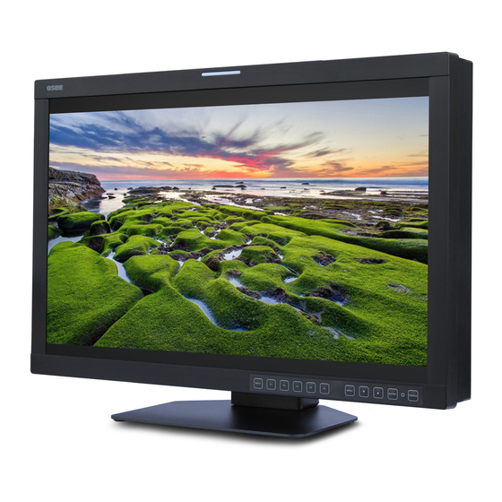
Overview Chapter 1 Overview The XCM-240 series LCD Monitor are high performance broadcast monitor tailoring most applications from program production, intensive upload/download, playout to studio and intensive monitoring all sorts of business in TV Stations. The front frame of the unit comes in a slim bezel design made from rubber mold. - Page 8 Overview Using 10-bit signal processing technology plus advanced conversion technology between the interlacing and the progressive Featuring PBP and PIP, dual 3G-SDI capable under PBP mode Supporting waveform/vector scope, audio metering bar, TC, IMD and Supporting varied color temperature, varied scan modes, flexibility in marker setting, Blue Only/Monochrome mode Functionality ...
-
Page 9: Chapter 2 Safety
Safety Chapter 2 Safety FCC Caution Any Changes or modifications not expressly approved by the party responsible for compliance could void the user's authority to operate the equipment. This device complies with part 15 of the FCC Rules. Operation is subject to the following two conditions: (1) This device may not cause harmful interference, and (2) this device must accept any interference received, including interference that may cause undesired operation. - Page 10 Safety Warnings Read, keep and follow all of these instructions for your safety. Heed all warnings. Device Install in accordance with the manufacturer's instructions. Do not beat with a hard object or scratch the LCD display. Do not make the freeze picture displaying on the screen time too long, ...
- Page 11 Safety heat. A nameplate indicating operating voltage, etc., is located on the rear panel. The socket-outlet shall be installed near the equipment and shall be easily accessible. Power Supply Cord Do not defeat the safety purpose of the polarized or grounding-type plug.
-
Page 13: Chapter 3 Unpack And Installation
When unpacking the components of XCM-240 monitor, please verify that none of the components listed in Table 3.1 are damaged or lack. If there is any missing, contact your distributors or Beijing Osee Digital Technology Ltd. for it. Table 3-1 Packing List... - Page 14 Unpack and Installation As a final step, turn on each screen of the device by pressing the corresponding power switch located on the front panel. The pedestal and the monitor are packaged separately. Connect a standard signal lines to the corresponding input port. All BNC connector impedance must be 75Ω.
-
Page 15: Chapter 4 Xcm-240 Features
XCM-240 Features Chapter 4 XCM-240 Features This chapter describes the features of XCM-240 monitor. The features of XCM-240monitor are as shown in Figure 4-1 after installed and powered on: Status Information SDI1 AFD CC 1080I59.94 Area Marker Safe Marker Audio Meter 1 2 3 4 5 6 7 8 Center Marker KEY INHIBIT... - Page 16 XCM-240 Features image. You can set whether to display it or not in MARKER menu. Audio Meter It is displayed for audio monitoring. You can set its groups, direction, position and mode in AUDIO menu. Timecode It is displayed at the bottom of the image, the format is HH:MM:SS:FF, if there is no timecode available, the monitor will display --:--:--:--.
-
Page 17: Front Panel Features
XCM-240 Features 4.1 Front Panel Features It will introduce the arrangement and the operations of the buttons in front of the panel in the following. 4.1.1 Arrangement of Front Panel There are a series of buttons at the bottom of the screen, and these buttons are used to control the screen menu items. -
Page 18: Operation Of Front Panel
XCM-240 Features 4.1.2 Operation of Front Panel The functionality and usage of the buttons at the front panel are as follows: INPUT Select the input signal. Press this button to display the input source menu at the right top corner of the screen, as shown in Figure 4.1-2. Use it to select an input signal source, press it again to toggle among these input signal items. - Page 19 XCM-240 Features This button is a FUNCTION button. The function can be set via the FUNCTION menu. Open the FUNCTION menu after the first time, the selected function will remain. OPERATION: Press F1 to display the function menu list in the center of the screen, as shown in Figure 4.1-4.
- Page 20 XCM-240 Features factory originals, as shown in Figure 4.1-5. FACTORY RESET Factory Reset Now? Figure 4.1-5 Reset Menu List It is used to activate to F3 function button. The operation is as the same as F1's. It is used to activate to F4 function button. The operation is as the same as F1's.
- Page 21 XCM-240 Features Enter into the next level menu: press ENTER button, you will enter into the menu item as this relationship: the Main menu list sub-menu list sub-menu value list, the current editable object is in yellow control icon; ...
-
Page 22: Rear Panel Features
XCM-240 Features selection list of a screen may not be shown all simultaneously. Power Used to power on or standby, and the light in the button will indicate the status of the power. If the light is green, the monitor is powered on, if the light is flashing, the monitor is standby. -
Page 23: Operations Of Rear Panel
XCM-240 Features The interfaces numbered from 1 to 8 in red dotted rectangle are described as follows: Power Switch Power Input Video Input: SDI1 IN, SDI2 IN HDMI Input Video Output: SDI1 OUT, SDI2 OUT Ethernet GPI interface RS485 In/Out Audio Input Audio Output Headphone Output Connector (3.5mm stereo Jack) - Page 24 XCM-240 Features ON OFF Figure 4.2-2 Power Switch Power Input It provides one power input interface, the specification is 19V4.74ADC. The corresponding indicator is at the front panel. If the light is green, the monitor is powered on, if the light is flashing, the monitor is standby, and if the light is off, the monitor is powered off.
- Page 25 XCM-240 Features Pin No. Channel Value Pin 1 GPI1 Pin 2 GPI2 Pin 3 GPI3 Pin 4 GPI4 Pin 5 GPI5 Pin 6 GPI6 Pin 7 Pin 8 IN/ OUT RS485 Interface (RJ-45) Support for dynamic IMD and updating the new firmware. The Comparison of Pins and Input/output connectors for RS485 is shown as in Table 4.2-2: Table 4.2-2 The Comparison of Pins and Input/output connectors for...
- Page 26 XCM-240 Features It provides two pairs of Composited Video input/output interfaces, and a group of component signals. It will transmit the corresponding component signal according to the selection of the signal source. As shown in Figure 4.2-3, the relationship of the signal sources and the interfaces are shown as in Table 4.2-3: Table 4.2-3 The Relationship of the Signal Sources and Input/output Interfaces...
-
Page 27: Supported Signal Format
XCM-240 Features 4.3 Supported Signal Format The supported signal format for this device is as shown in Table 4.3-1: Table 4.3-1 Supported Signal Format VIDEO HDMI YPBPR NTSC 480I60/59.94 576I50 480P60/59.94 ... - Page 28 XCM-240 Features VIDEO HDMI YPBPR UXGA(1600X1200) UXGA+(1680X1050) WUXGA(1920X1080) WUXGA(1920X1200) ...
-
Page 29: Chapter 5 Functionality Of The Main Menu
Functionality of the Main Menu Chapter 5 Functionality of the Main Menu This chapter describes the structure and functionality of the main menu, and introduces how to modify and customize the menu settings. The main menu includes the following menu items, as shown in Figure5-1. Figure 5-1 Main Menu 5.1 Main Menu Press the MENU button at the bottom of the front panel, the main menu is... - Page 30 Functionality of the Main Menu The menu interface is divided into three parts: Main Menu List It contains the title of the Main menu and several sub-menu items. The title of this list is MAIN. Press UP or DOWN to access the corresponding menu item.
- Page 31 Functionality of the Main Menu Figure 5.1-3 A Main Menu Item Is Selected when in the sub-menu item, it shows that this sub-menu item is selected, and the control icon is displayed as a yellow rectangle in front of it, as shown in Figure 5.1-4: Figure 5.1-4 A Sub-menu Item Is Selected ...
-
Page 32: Status Menu
Functionality of the Main Menu The following will introduce the contents and functionality of these sub-menu items in sorts. 5.1.1 STATUS Menu The STATUS menu items are used to describe the current status information of the monitor, the menu items are as shown in Figure 5.1-6: MAIN STATUS INPUT... -
Page 33: Input Select Menu
Functionality of the Main Menu Items Default Value Domain Range Description FAST OFF/ON Show the fast mode. MODE Show screen SD ASPECT 16:9 16:9/4:3 Aspect Ratio. Show the production MODEL XCM-240-3HSV model. SERIAL Show serial XCM2402013070001 NUMBER number. 192.168.1.86 Show the IP address. ADDRESS Show color... -
Page 34: Marker Menu
Functionality of the Main Menu The relationship of Items, Default Value, Domain Range and Description of the sub-item is shown in Table 5.1-2: Table 5.1-2 The Description of INPUT SELECT Menu Items Default Items Domain Range Description Value SDI1 ON/OFF Enable/Disable SDI1 input SDI2 ON/OFF... - Page 35 Functionality of the Main Menu of the sub-item is shown in Table 5.1-3: Table 5.1-3 The Description of MARKER Menu Items Default Items Domain Range Description Value Set whether to show all of the markers. It is the main switch for MARKER OFF/ON area...
-
Page 36: Audio Menu
Functionality of the Main Menu Default Items Domain Range Description Value cross hatch. OFF: Normal background, use line for area marker edge only Set the transparency of MARKER MAT HALF: 50% area marker mat. Background brightness BLACK: all black Set whether to show the CROSS HATCH OFF OFF/ON... - Page 37 Functionality of the Main Menu MAIN AUDIO AUDIO SOURCE AUDIO1 STATUS INPUT SELECT SPEAK OUT L EBD CH1 MARKER SPEAK OUT R EBD CH1 AUDIO AUDIO METER DISPALY METER SELECT CH1-2 CLOSE CAPTION METER DIRECTION HORIZONTAL CONFIG METER POSITION COLOR TEMP METER DIS MODE MODE1 FUNCTION KEY...
- Page 38 Functionality of the Main Menu Default Items Domain Range Description Value G1+G2 G1+G3 G1+G4 G2+G3 G2+G4 G3+G4 G1-G4 METER VERTICAL Select displayed VERTICAL DIRECTION HORIZONTAL direction of audio meter. When the value of METER DIRECTION is VERTICAL choose followings...
-
Page 39: Display Menu
Functionality of the Main Menu 5.1.5 DISPLAY Menu The DISPLAY menu items are used to adjust the parameters displayed on the screen, the menu items are as shown in Figure 5.1-10: MAIN DISPLAY STATUS DISPLAY AUTO STATUS INPUT SELECT AFD DISPLAY MARKER WAVE FORM TYPE WAVE FORM... - Page 40 Functionality of the Main Menu Default Items Domain Range Description Value TYPE MODE2 mode1, mode2, vector100, VECT100 vector75 and wave form. VECT75 WAVE FORM Set whether to show line wave, LINE WAVE OFF/ON as shown in Figure 5.1-11. LINE WAVE shown...
-
Page 41: Close Caption Menu
Functionality of the Main Menu Input Signal Default Domain Range 1080p 42~1121 The comparison of a normal WFM/Vector and a Line WFM is as shown in Figure 5.1-11: LINE WFM Figure 5.1-11 The LINE WFM and the WFM You can call out the vectorscope or wave form and configure its display mode through DISPLAYWAVE FORM TYPE, and configure its display position through DISPLAY WFM POSITION. -
Page 42: Config Menu
Functionality of the Main Menu MAIN CLOSE CAPTION CLOSED CAPTION STATUS INPUT SELECT SDI CC LOG MARKER AUDIO DISPALY CLOSE CAPTION CONFIG COLOR TEMP FUNCTION KEY KEY INHIBIT Figure 5.1-12 CLOSE CAPTION Menu The relationship of Items, Default Value, Domain Range and Description of the sub-item is shown in Table 5.1-7: Table 5.1-7 The Description of CLOSE CAPTION Menu Items Default... - Page 43 Functionality of the Main Menu MAIN CONFIG FAST MODE STATUS INPUT SELECT FILM MODE DETECT MARKER SUB IN TYPE AUDIO SUB IN SELECT SDI1 DISPALY PIP SIZE LARGE CLOSE CAPTION PIP POSITION HORIZONTAL CONFIG BACKLIGHT COLOR TEMP AUTO STANDBY FUNCTION KEY APPEATURE LOCK NUMBER LANGUAGE...
- Page 44 Functionality of the Main Menu Default Items Domain Range Description Value TOP RIGHT TOP LEFT BACK LIGHT 0~30 Adjust the back light Set whether open the AUTO STANDBY OFF OFF/ON standby mode. picture APPERTURE 0~24 sharpness LOCK NUMBER XXXXXXXX -- Set the lock number Select...
- Page 45 Functionality of the Main Menu Main Slave Picture Picture Figure 5.1-15 PBP Mode In PBP mode, it displays the WFM or Audio Meter only for the signal of the current picture. The current picture is labeled by a triangle, as shown in Figure 5.1-15, at the bottom center of the picture.
-
Page 46: Color Temp Menu
Functionality of the Main Menu right corner of the screen. When the AUTO STANDBY is set to ON, the device will be standby when the signal is disappeared for 60s. The length of LOCK NUMBER is up to 8 characters, you can use the combination of these characters: number (0 to 9) and letter (A to Z). -
Page 47: Function Key Menu
Functionality of the Main Menu Items Default Value Domain Range Description USER1: Customized by user USER2: Customized by user COLOR D32: 3200K Set color temperature TEMP D50: 5000K D56: 5600K D65: 6500K D93: 9300K ... - Page 48 Functionality of the Main Menu MAIN FUNCTION KEY SCAN STATUS INPUT SELECT NATIVE MARKER ASPECT AUDIO DISPALY CLOSE CAPTION CONFIG COLOR TEMP FUNCTION KEY KEY INHIBIT Figure 5.1-17 FUNCTION KEY Menu The relationship of Items, Default Value, Domain Range and Description of the sub-item is shown in Table 5.1-11: Table 5.1-11 The Description of FUNCTION KEY Menu Items Items Default Value Domain Range...
-
Page 49: Gpi Menu
Functionality of the Main Menu OVER: Zooms in/out of the image to 96% of its original size without changing the aspect ratio. NORMAL: Zooms in/out of the image without changing the aspect ratio. UNDER: Zooms in/out of the image without changing the aspect ratio. - Page 50 Functionality of the Main Menu Items Default Value Domain Range Description BLUE ONLY, MONO, DELAY, DELAY, DELAY, SDI1, SDI2, LINE1, LINE2, HDMI, TALLY GREEN, TALLY RED GPI2 TALLY RED the same as GPI1 Set a function to GPI2 GPI3 UNDEF the same as GPI1 Set a function to GPI3 GPI4 UNDEF...
-
Page 51: Imd Menu
Functionality of the Main Menu Items Function Trigger Switch scan mode between UNDER SCAN Low: UNDER; High: NORMAL under and normal. Switch between blue only Low: BLUE ONLY; High: BLUE ONLY and normal. NORMAL Switch between native and Low: NATIVE(In center); High: NATIVE normal. - Page 52 Functionality of the Main Menu MAIN IMD DISPLAY STATUS INPUT SELECT IMD COLOR MARKER IMD CHARACTER XXXXXXXXXXXXXXXX AUDIO IMD PROTOCOL LOCAL DISPALY IMD ID CLOSE CAPTION IMD NAME XXXXXXXXXXXXXXXX CONFIG BAUD RATE 38400 COLOR TEMP LED TALLY FUNCTION KEY OSD TALLY MODE IMD TALLY MODE TALLY SOURCE STANDARD...
- Page 53 Functionality of the Main Menu Default Items Domain Range Description Value Set the ID number for IMD ID 0~255 each monitor Set an IMD name for IMD NAME XXXXXXXX each screen. 2400/4800/9600/19200 Select a baud rate for BAUD RATE 38400 /38400/57600/115200 communication.
-
Page 54: Key Inhibit Menu
Functionality of the Main Menu 5.1.12 KEY INHIBIT Menu The KEY INHIBIT menu items are used to adjust the parameters displayed on the screen, the menu items are as shown in Figure 5.1-10: MAIN KEY INHIBIT KEY INHIBIT STATUS INPUT SELECT MARKER AUDIO DISPALY... - Page 55 Functionality of the Main Menu following buttons: MENU, UP, DOWN, ENTER. Operations to the Main menu Display the Main Menu Press MENU button to enter into the main menu, it displays at the top left corner of the screen. ...
- Page 56 Functionality of the Main Menu Display the sub-menu item After display the Main menu, press UP or DOWN button to select a menu item, and the right part displays its sub-menu items according to the current selected menu item. ...
- Page 57 Functionality of the Main Menu The value in white color is modifiable, and the value in blue color is unmodifiable. Selecting the Menu Language You can select one of languages (English or Chinese) for displaying the menu. The default language for the menu is ENGLISH. The following will teach you how to switch to Chinese.
- Page 58 Functionality of the Main Menu shown in Figure 5.2-4, press ENTER button to confirm the modification. 主菜单 系统配置 快速模式 关闭 状态显示 输入设置 电影模式检测 关闭 标记设置 子画面类型 音频设置 子画面输入源 SDI1 显示设置 小 PIP大小 隐藏字幕 右下 PIP位置 系统配置 背光 色彩配置 自动关机 关闭 功能键设置...
-
Page 59: Chapter 6 Network Control
Network Control Chapter 6 Network Control XCM-240 supports network interface. Connect a computer with XCM-240 through this interface to achieve the network control to XCM-240. The network address of the computer which is connected with XCM-240 and the network address of XCM-240 must be in the same segment. This chapter will introduce how to set and check the parameters of XCM-240 in Internet Explorer. -
Page 60: Menu Control
Network Control 6.2 Menu Control Open the management interface as shown in Figure 6.2-1, the menu items listed in the left part are almost as the same as the main menu items. Figure 6.2-1 Management Interface As shown in Figure 6.2-1, the management interface is divided into the following parts: Input Source Selection Button It is used to selecting an input source as the input signal, such as: SDI1,... -
Page 61: Adjust Menu
Network Control Parameter list It shows the parameter names, values and operation buttons of the selected navigation menu, as shown in the red rectangle in Figure 6.2-2. The title in the yellow rectangle of the parameter list and the parameter list will change with the navigation menu when switched. - Page 62 Network Control Figure 6.2-3 ADJUST Menu The relationship of Items, Default Value, Domain Range and Description of the sub-item is shown in Table 6.2-3: Table 6.2-1 The Description of ADJUST Menu Items Items Default Value Domain Range Description Adjust picture CONTRAST 0~100 contrast...
-
Page 63: Video Display Menu
Network Control Items Default Value Domain Range Description picture displaying mode in full WIN SOURCE MAIN MAIN/SUB mode or in sub-picture mode VOLUME 0~31 Adjust the volume 6.2.2 VIDEO DISPLAY Menu It will introduce VIDEO DISPLAY menu. Click VIDEO DISPLAY button at the left navigation menu list, it will display the video display parameters, as shown in Figure 6.2-5: Figure 6.2-4 VIDEO DISPLAY Menu The relationship of Items, Default Value, Domain Range and Description... -
Page 64: Other Menus
Network Control Figure 6.2-5 System Menu The relationship of Items, Default Value, Domain Range and Description of the sub-item is shown in Table 6.2-3: Table 6.2-3 The Description of System Menu Items Domain Items Default Value Description Range 192.168.1.86 IP address MASK 255.255.255.0 Subnet mask... -
Page 65: Parameter Settings
Network Control “Chapter 5 Functionality of the Main Menu” for the details about STATUS, VIDEO CONFIG, AUDIO CONFIG, MARKER, DISPLAY, USER CONFIG, and COLOR TEMPERATURE. 6.3 Parameter Settings It will introduce how to modify parameter values in management interface in the followings. - Page 66 Network Control Click button to display the drop-down value list for the parameter, as shown in Figure 6.3-3, for example, modify “CH1-2” to “G1”. Figure 6.3-3 Display the Drop Down Value List of Meter Select(S) Click button to confirm the selection and the page is refreshed. You can check the modification on the screen menu, the results are the same as shown in Figure 6.3-4 and Figure 6.3-5: Figure 6.3-4 Modify the Value of a Parameter...
- Page 67 Network Control The volume can be checked and modified in adjust menu on screen adjustment, or in Volume item of ADJUST menu in management interface. MAIN AUDIO AUDIO SOURCE AUDIO1 STATUS INPUT SELECT SPEAK OUT L EBD CH1 MARKER SPEAK OUT R EBD CH1 AUDIO...
-
Page 69: Chapter 7 Specifications
Specifications Chapter 7 Specifications Product detailed information Specification Values LCD Dimension 24”, 569.9(H) x 380.7(V) x 97.4(D) Aspect Ratio 16:10 Display Area(mm) 518.4(H)×324.0(V) Viewing Angle 178°(H)x178°(V) Color Depth 1.073G colors (RGB 10-bits) Resolution 1920(H)×1200(V) Pixel Pitch(mm) 0.270(H)×0.270(V) Contrast 1000:1(Typ.) Luminance (cd/㎡) 250 (Typ.) Response Time (ms Typ.) <6 Backlight... - Page 70 Specifications Specification Values 3G-SDI /HD-SDI /SDI-SDI Input/Output SMPTE 424M, SMPTE 292M, SMPTE 259M, Signal Type SMPTE 297M Connector BNC per IEC 169-8 Impedance 75Ω >18 dB 5 to 270 MHz Return Loss >15 dB 270 MHz to 1.5 GHz >10 dB up to 3 GHz Maximum Signal Level 800 mV pk-pk 10% Signal Amplitude...
- Page 71 Specifications OVERSCAN NATIVE FULL/NORMAL Refresh Color OUTPUT Rate Matrix Input Output Input Output INPUT ALL NORMAL 1024X768 1024X768 720P24 1216X684 1366X768 1280x720 1280x720 1280x720 1366X768 720P25 1216X684 1366X768 1280x720 1280x720 1280x720 1366X768 720P30 1216X684 1366X768 1280x720 1280x720 1280x720 1366X768 720P50 1216X684 1366X768 1280x720...
- Page 72 Specifications Figure 7-1 Front Panel(Unit: mm) Figure 7-2 Rear Panel(Unit: mm)
- Page 73 Specifications Figure 7-3 Top View(Unit: mm) Figure 7-4 Side View(Unit: mm) Specifications are subject to change without notice. ------------------No Text Below------------------...
- Page 74 FOR MORE INFORMATION PLEASE VISIT: http://www.osee-dig.com/ OSEE TECHNOLOGY CO., LTD. No.22 Building, No.68 zone, Beiqing Road, Haidian District, Beijing, China Tel: (+86) 010-62434168, Fax: (+86) 010-62434169 E-mail: sales@osee-dig.com...
Need help?
Do you have a question about the XCM240LCDM and is the answer not in the manual?
Questions and answers