Table of Contents
Advertisement
Quick Links
Advertisement
Table of Contents

Subscribe to Our Youtube Channel
Related Manuals for OSEE RMM1024


Summary of Contents for OSEE RMM1024
- Page 1 RMM1024 Monitor User Manual...
- Page 3 MODEL: RMM1024 Monitor VERSION: V010000 RELEASE DATE: 2013-12-20 Company Beijing Osee Digital Technology Ltd. Customer Support Address: No.22 Building, No.68 zone, Beiqing Road, Haidian District, Beijing, China Post Code: 100094 Tel: 010-62434168 Fax: 010-62434169 http://www.osee-dig.com/ E-mail: sales@osee-dig.com...
-
Page 4: Contents
The user manual applies to the following device types: RMM1024-3HSV RMM1024-HSV RMM1024-SV The images of RMM1024-3HSV are adopted in the following descriptions. Any of the different specifications between the device types are elaborated. Before reading the manual, please confirm the device type. -
Page 5: Table Of Contents
Chapter 1 Overview ..................1 Chapter 2 Safety ..................... 3 Chapter 3 Unpack and Installation ............... 5 Chapter 4 RMM1024 Features ............... 7 4.1 Front Panel Features ................8 4.1.1 Arrangement of Front Panel ............. 9 ... - Page 6 Chapter 7 Specifications ................61 II ...
-
Page 7: Chapter 1 Overview
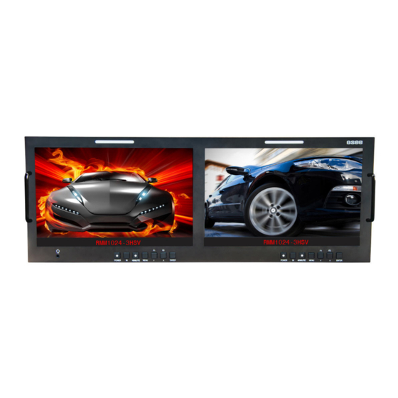
Overview Chapter 1 Overview RMM1024 is a 10.1”, 2-screen, 4RU high full HD LCD monitor. It offers a full resolution 1920X1200 LCD panel, with wide viewing angle and wide color gamut. It supports the video signal of analog composite/3G/HD/SD-SDI and HDMI. - Page 8 Overview Functionality Audio phase meter and phase alarm display 16 channels embedded audio level meter, the channel number and the dB value can be displayed Supports various markers: Center Marker, Area Marker and Safe Marker Supports TSL/IMAGE VIDEO dynamic TALLY protocol ...
-
Page 9: Chapter 2 Safety
Safety Chapter 2 Safety Read, keep and follow all of these instructions for your safety. Heed all warnings. Monitor Do not beat with a hard object or scratch the LCD display. Do not make the freeze picture displaying on the screen time too long, ... - Page 10 Safety Do not expose the unit to rain or moisture. Do not use this unit near any heat sources such as radiators, heat registers, stoves, or other apparatus (including amplifiers) that product heat. A nameplate indicating operating voltage, etc., is located on the rear panel.
-
Page 11: Chapter 3 Unpack And Installation
Connect AC power source using the included power cord. Connect the power cord to the rear panel. Fasten the power protect accessory. As a final step, turn on each screen of the RMM1024 by pressing the corresponding power switch located on the front panel. 5 ... -
Page 13: Chapter 4 Rmm1024 Features
Chapter 4 RMM1024 Features This chapter describes the features of RMM1024 monitor. The features of RMM1024 monitor are as shown in Figure 4-1 after installed and powered on: Figure 4-1 Features of RMM1024 Monitor Tally light: this LED light is at the top center of the front panel, and you can judge the monitor status by the color of Tally light. -
Page 14: Front Panel Features
RMM1024 Features Center Marker: it is displayed in the center of the screen, and marks the center of the image. You can set whether to display it or not in MARKER menu. Audio Meter: it is displayed for audio monitoring. You can set its groups, direction, position and mode in AUDIO menu. -
Page 15: Arrangement Of Front Panel
F2/∧ ENTER Stand directly in front of a RMM1024, usually, the left screen is called No.1 screen, and the right screen is called No.2 screen. The buttons of Screen No.2 act as the same as the buttons of Screen No.1, and just effect on the current screen. -
Page 16: Operation Of Front Panel
RMM1024 Features 4.1.2 Operation of Front Panel The functionality and usage of the buttons at the front panel are as follows: Power Used to power on or standby, and the light in the button will indicate the status of the power. If the light is green, the monitor is powered on, if the light is flashing, the monitor is standby. - Page 17 RMM1024 Features Figure 4.1-3 Correspondence between Source Menu and Interface /MUTE This button can achieve the following two functions: : Audio monitor button. Toggle this button to enable or disable the audio monitor, and the light in the button will indicate the status of audio monitoring.
- Page 18 RMM1024 Features After you have loaded the Audio Monitor Menu, it will be closed automatically if you do nothing operation with it in 10s. MENU It is used to activate the Main menu. Press this button to do some operations with the Main menu, it includes the following operations: ...
- Page 19 RMM1024 Features Figure 4.1-6 Function Menu List After you have loaded the function menu list, it will be closed automatically if you do nothing operation with it in 10s. If the value related to the function button can’t be modified, the value shows in blue.
- Page 20 RMM1024 Features ENTER button achieve the following functions: Enter into the next level menu: press ENTER button, you will enter into the menu item as this relationship: the Main menu list sub-menu list sub-menu value list, the current editable object is in yellow control icon;...
-
Page 21: Rear Panel Features
As shown in Figure 4.2-1, there are various input and output interfaces at the rear panel of RMM1024 monitor. Figure 4.2-1 The Rear Panel of RMM1024 Monitor The interfaces numbered from 1 to 8 in red dotted rectangle are described... -
Page 22: Operations Of Rear Panel
RMM1024 Features Ethernet RS485 In/Out Tally Input 4.2.2 Operations of Rear Panel The details of these interfaces at the rear panel are described as follows: Power Input It provides one power input interface, the specification is 5~12VDC. The corresponding indicator is at the front panel. If the light is green, the monitor is powered on, if the light is flashing, the monitor is standby, and if the light is off, the monitor is powered off. - Page 23 RMM1024 Features Ethernet (RJ-45) It provides one 10/100M Ethernet connector. It is used to connect with a computer to modify the network settings. IN/ OUT RS485 Interface (RJ-45) Support for dynamic UMD and updating the new firmware. The Comparison of Pins and Input/output connectors for RS485 is shown as in Table 4.2-1:...
-
Page 24: Supported Signal Format
RMM1024 Features Thereinto, the tally light will display in different color according to its pin connection way, the relationship is shown in Table 4.2-2: Table 4.2-3 The Relationship of Tally Light Color and Pins Screen 1 Screen 2 Tally Light... - Page 25 RMM1024 Features VIDEO HDMI 1080I50 1080I60/59.94 1080P24/23.97 1080P25 1080P30/29.97 1080P50 1080P60/59.94 VGA(640X480) SVGA(800X600) XGA(1024X768) SXGA(1280X1024) WXGA(1360X768) WXGA+(1440X900) WXGA+(1400X1050) UXGA(1600X1200) ...
-
Page 27: Chapter 5 Functionality Of The Main Menu
Functionality of the Main Menu Chapter 5 Functionality of the Main Menu This chapter describes the structure and functionality of the main menu, and introduces how to modify and customize the menu settings. The main menu includes the following menu items, as shown in Figure5-1. MAIN STATUS INPUT... - Page 28 Functionality of the Main Menu The menu interface is divided into three parts: Main Menu List: it contains the several sub-menu items. The title of this list is MAIN. Press Up(∧) or Down(∨) to access the corresponding menu item. Sub-menu value list: as shown in Figure 5.1-2, it lists the control icon, sub-menu item and the value of the item.
- Page 29 Functionality of the Main Menu Figure 5.1-3 A Main Menu Item Is Selected when in the sub-menu item, it shows that this sub-menu item is selected, and the control icon is displayed as a yellow rectangle in front of it, as shown in Figure 5.1-4: Figure 5.1-4 A Sub-menu Item Is Selected ...
-
Page 30: Status Menu
Functionality of the Main Menu Figure 5.1-5 A Sub-menu Item Value Is Selected The following will introduce the contents and functionality of these sub-menu items in sorts. 5.1.1 STATUS Menu The STATUS menu items are used to describe the current status information of the monitor, the menu items are as shown in Figure 5.1-6: Figure 5.1-6 STATUS Menu 24 ... - Page 31 MODE UNDER FAST OFF/ON Show the fast mode. MODE Show screen SD ASPECT 16:9 16:9/4:3 Aspect Ratio. Show the production MODEL RMM1024-3HSV model. SERIAL Show serial RMM10242013070001 -- NUMBER number. 192.168.1.86 Show the IP address. ADDRESS Show color COLOR 2013-12-9.1...
-
Page 32: Input Select Menu
Functionality of the Main Menu 5.1.2 INPUT SELECT Menu The INPUT SELECT menu items are used to set the source of the input signals, the menu items are as shown in Figure 5.1-7: MAIN INPUT SELECT SDI1 STATUS INPUT SELECT SDI2 MARKER LINE1... -
Page 33: Marker Menu
Functionality of the Main Menu 5.1.3 MARKER Menu The MARKER menu items are used to adjust the marker parameters, the menu items are as shown in Figure 5.1-8: MAIN MARKER MARKER STATUS INPUT SELECT AREA MARKER MARKER CENTER MARKER AUDIO SAFETY MARKER DISPALY MARKER LEVEL... - Page 34 Functionality of the Main Menu Default Items Domain Range Description Value aspect ratio according to aspect is 16:9, images the display aspect ratio. show with the following scale: OFF: close area marker 15:9 14:9 13:9 ...
-
Page 35: Audio Menu
Functionality of the Main Menu The AREA MARKER, CENTER MARKER and SAFETY MARKER feature are available only when the MARKER item is set to ON. The marker will not display in PBP mode even if you have opened the marker switch. - Page 36 Functionality of the Main Menu Default Items Domain Range Description Value signal2 select only UNDEF: no signal UNDEF, AUDIO1 AUDIO2. Left speaker, select a When the audio source is SPEAK EBD CH1 EBD, the range of this item channel according to the OUT L is EDB CH1~ EDB CH16.
-
Page 37: Display Menu
Functionality of the Main Menu Default Items Domain Range Description Value MODE1: simple audio meter MODE2: audio meter METER DIS Select displayed MODE1 with channel number MODE mode for audio meter. MODE3: audio meter with channel number and dB value Select reference... - Page 38 Functionality of the Main Menu Table 5.1-5 The Description of DISPLAY SETUP Menu Items Default Items Domain Range Description Value Set whether to display STD information. If the signal input is not equal to STATUS "No signal" and this item is auto, AUTO OFF/ON/AUTO DISPLAY...
-
Page 39: Close Caption Menu
Functionality of the Main Menu Table 5.1-6 The Description for LINE WFM Item Input Signal Default Domain Range 576i50 23~623 480i60 22~524 720p 26~745 1080i50 1080i60/59.94 21~1123 1080sf23/23.97 1035i60 41~1120 1080p 42~1121 Only in PIP mode or PBP mode, you can call out the vectorscope or wave form, configure its size through DISPLAYWAVE FORM SIZE, configure its display mode through DISPLAYWAVE FORM TYPE, and configure its display position through CONFIGIMD POSITION. -
Page 40: Config Menu
Functionality of the Main Menu MAIN CLOSE CAPTION CLOSED CAPTION STATUS INPUT SELECT SDI CC LOG MARKER AUDIO DISPALY CLOSE CAPTION CONFIG COLOR TEMP FUNCTION KEY Figure 5.1-11 CLOSE CAPTION Menu The relationship of Items, Default Value, Domain Range and Description of the sub-item is shown in Table 5.1-7: Table 5.1-7 The Description of CLOSE CAPTION Menu Items Default... - Page 41 Functionality of the Main Menu Figure 5.1-12 CONFIG Menu The relationship of Items, Default Value, Domain Range and Description of the sub-item is shown in Table 5.1-8: Table 5.1-8 The Description of CONFIG Menu Items Default Items Domain Range Description Value Set whether in fast FAST MODE...
- Page 42 Functionality of the Main Menu Default Items Domain Range Description Value BOT LEFT: bottom left BOT RIGHT: PIP POSITION BOT LEFT Set the position of PIP bottom right TOP RIGHT TOP LEFT BACK LIGHT 0~30 Adjust the back light Set whether open the AUTO STANDBY OFF OFF/ON...
- Page 43 Functionality of the Main Menu is as shown Figure 5.1-14: Figure 5.1-14 PBP Mode Scope for the slave picture The selection scope of the signal source for the slave picture will be changing with the main picture's s ource, as shown in Table 5.1-9: Table 5.1-9 The Relationship of the Signal Source for Slave Picture and Main Picture Signal Source for...
-
Page 44: Color Temp Menu
Functionality of the Main Menu Figure 5.1-15 The Slave Picture Is Displayed as WFM The length of LOCK NUMBER is up to 8 characters, you can use the combination of these characters: number (0 to 9) and letter (A to Z). Press ENTER to edit the LOCK NUMBER, than use ∧(Up) and ∨(Down) to select characters, than press ENTER to go to next character, press MENU to exit editor. - Page 45 Functionality of the Main Menu The relationship of Items, Default Value, Domain Range and Description of the sub-item is shown in Table 5.1-10: Table 5.1-10 The Description of COLOR TEMP Menu Items Items Default Value Domain Range Description USER1: Customized by user USER2: ...
-
Page 46: Function Key Menu
Functionality of the Main Menu 5.1.9 FUNCTION KEY Menu The FUNCTION KEY menu items are used to define parameters to F1 and F2, the menu items are as shown in Figure 5.1-17: MAIN FUNCTION KEY SCAN STATUS INPUT SELECT MARKER AUDIO DISPALY CLOSE CAPTION... -
Page 47: Imd Menu
Functionality of the Main Menu NORMAL OVER UNDER Set the function button as [SCAN], press the button continuously to activate various scan modes. OVER: Zooms in/out of the image to 96% of its original size without changing the aspect ratio. ... - Page 48 Functionality of the Main Menu Table 5.1-12 The Description of IMD Menu Items Default Items Domain Range Description Value Set whether to display IMD DISPLAY ON OFF/ON IMD CHARACTER on screen. Set the color for IMD GREEN IMD COLOR YELLOW ...
-
Page 49: Menu Settings
Functionality of the Main Menu Default Items Domain Range Description Value will determine the state which is selected. TALLY STANDARD/IMAGE Select the source for STANDARD SOURCE IDEO/TSL LED tally source The length of IMD NAME and IMD CHARACTER is up to 16 characters. The character range is from 0x00 to 0x7F of ASCII. - Page 50 Functionality of the Main Menu MAIN STATUS INPUT SDI1 STATUS INPUT SELECT FORMAT NO SIGNAL MARKER COLOR TEMP AUDIO SCAN MODE OVER DISPALY FAST MODE CLOSE CAPTION MODEL RM1024-3HSV CONFIG SERIAL NUMBER RM10242013070001 COLOR TEMP IP ADDRESS 192.168.1.86 FUNCTION KEY COLOR VERSION 65535 -255 -255.65535 Figure 5.2-1 Selecting STATUS Menu...
- Page 51 Functionality of the Main Menu Back to menu item After entering to the sub-menu item value, press MENU button to back to menu items, or after setting the sub-menu item value and press Enter button to firm the modification, the control icon is back to the corresponding sub-menu item, as shown in Figure 5.2-2: INPUT SELECT SDI1...
- Page 52 Functionality of the Main Menu will teach you how to switch to Chinese. Operation: Step 1 Select CONFIG menu Press MENU button to display the OSD menu, click ∨(down) button to select CONFIG menu. Step 2 Select the value of the Language item Press ENTER button to get into the CONFIG menu items, and click ∨...
- Page 53 Functionality of the Main Menu Figure 5.2-4 Switching the Value of LANGUAGE Step 4 Exit the main menu Click MENU button to exit the main menu. 47 ...
-
Page 55: Chapter 6 Network Control
The network address of the computer which is connected with RMM1024 and the network address of RMM1024 must be in the same segment. This chapter will introduce how to set and check the parameters of RMM1024 in Internet Explorer. -
Page 56: Menu Control
Click “Monitor 1” to show the parameter values set in screen No.1, and click “Monitor 2” to show the parameter values set in screen No. 2. For a RMM1024 device, “Monitor 1” is corresponding to screen No.1, and “Monitor 2” is corresponding to screen No.2. Select a monitor before you set or check the parameters for it. - Page 57 Network Control Input Source Selection Button It is used to selecting an input source as the input signal, such as: SDI1, SDI2, LINE1, LINE2, HDMI. The selecting box of "Apply to All" at the right side is used to synchronize the settings of a monitor to another monitor.
-
Page 58: Adjust Menu
Network Control There may be a “(S)” icon followed by some parameter name in the parameter list, it is mean that this parameter is only a local parameter for the current selected monitor, otherwise, the parameter is global and the modification is valid for both screens. - Page 59 Network Control The relationship of Items, Default Value, Domain Range and Description of the sub-item is shown in Table 6.2-3: Table 6.2-1 The Description of ADJUST Menu Items Items Default Value Domain Range Description Adjust picture CONTRAST 0~100 contrast Adjust picture BRIGHTNESS 0~100...
-
Page 60: Video Display Menu
Network Control 6.2.2 VIDEO DISPLAY Menu It will introduce VIDEO DISPLAY menu. Click VIDEO DISPLAY button at the left navigation menu list, it will display the video display parameters, as shown in Figure 6.2-5: Figure 6.2-4 VIDEO DISPLAY Menu The relationship of Items, Default Value, Domain Range and Description of the sub-item is shown in Table 6.2-3: Table 6.2-2 The Description of VIDEO DISPLAY Menu Items Items... -
Page 61: Other Menus
Network Control Figure 6.2-5 System Menu The relationship of Items, Default Value, Domain Range and Description of the sub-item is shown in Table 6.2-3: Table 6.2-3 The Description of System Menu Items Domain Items Default Value Description Range 192.168.1.86 IP address MASK 255.255.255.0 Subnet mask... -
Page 62: Parameter Settings
Network Control the menu items in the Main menu on screen, there will be no further description about their meanings and value range in this chapter, refer to “Chapter 5 Functionality of the Main Menu” for the details about STATUS, VIDEO CONFIG, AUDIO CONFIG, MARKER, DISPLAY, USER CONFIG, and COLOR TEMPERATURE. - Page 63 Network Control Figure 6.3-2 Screen Main Menu for AUDIO Click button to display the drop-down value list for the parameter, as shown in Figure 6.3-3, for example, modify “CH1-2” to “G1”. Figure 6.3-3 Display the Drop Down Value List of Meter Select(S) 57 ...
- Page 64 Network Control Click button to confirm the selection and the page is refreshed. You can check the modification on the screen menu, the results are the same as shown in Figure 6.3-4 and Figure 6.3-5: Figure 6.3-4 Modify the Value of a Parameter ...
- Page 65 Network Control Figure 6.3-5 The Value is Modified Simultaneously on Screen Menu Likewise, if you modify the value of a parameter on screen menu first, you may check the same changing result in management interface through network connection. 59 ...
-
Page 67: Chapter 7 Specifications
Specifications Chapter 7 Specifications Product detailed information Specification Values Number of Screens Aspect Ratio 16:10 Display Area(mm) 216.81(H)×135.50(V) Viewing Angle 178°(H)x178°(V) Color Depth 16.7M colors (RGB 8-bits) Resolution 1920(H)×1200(V) Dot Pitch(mm) 0.113(H)×0.113(V) Contrast 800:1 400 typ. (5 points average) Brightness(cd/㎡) 340 min. - Page 68 Specifications Specification Values Stereo HEADPHONE (3.5mm stereo Jack) Dimensions The description of the product dimensions of RMM1024is shown as in the following figures: Figure 7-1 Front Panel(Unit: mm) Figure 7-2 Rear Panel(Unit: mm) 62 ...
- Page 69 Specifications Figure 7-3 Side View(Unit: mm) Specifications are subject to change without notice. ------------------No Text Below------------------ 63 ...
- Page 71 FOR MORE INFORMATION PLEASE VISIT: http://www.osee-dig.com/ No.22 Building, No.68 zone, Beiqing Road, Haidian District, Beijing, China Tel: (+86) 010-62434168, Fax: (+86) 010-62434169 E-mail: sales@osee-dig.com...
Need help?
Do you have a question about the RMM1024 and is the answer not in the manual?
Questions and answers