Table of Contents
Advertisement
Quick Links
Advertisement
Table of Contents

Related Manuals for OSEE RMD5733-HSC


Summary of Contents for OSEE RMD5733-HSC
- Page 1 RMD5733 USER MANUAL...
- Page 2 PRODUCT INFORMATION MODEL: RMD5733 LCD MONITOR Version: V040000 Release Date: 2010-1-22 COMPANY NAME Beijing Osee Digital Technology Ltd. CONTACT INFORMATION Address: Room 702, Tower D, Jinyujiahua Building, No.9, 3rd Shangdi Street, Haidian District, Beijing, China Post code:100085 Tel: 8610-62968823 Fax: 8610-62977165 Http://www.osee-dig.com...
- Page 3 The user manual applies to the following device types: RMD5733-HSC RMD5733-SC RMD5733-V The images of RMD5733-HSC are adopted in the following descriptions. Any of the different specifications between the device types are elaborated. Before reading the manual, please confirm the device type.
-
Page 4: Table Of Contents
Contents Chapter 1 Product Overview ....................1 Chapter 2 Safety Precaution for Use .................. 2 Chapter 3 Unpacking and Installation ................3 Chapter 4 Using the RMD5733 ................... 4 4.1 Status Display of the Screen ......................4 4.2 Front Panel Controls ........................5 4.3 Quick Button Descriptions ...................... -
Page 5: Chapter 1 Product Overview
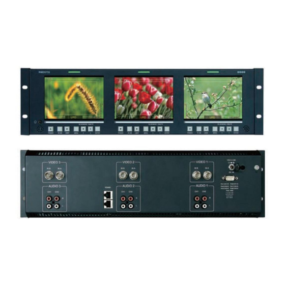
Support FPGA and MCU upgrade via RS485. Product Number Description RMD5733-HSC Three monitors: each monitor includes two video inputs (support HD-SDI / SD-SDI / CVBS), four external audio input connectors. One RS485 input (RJ45), One RS485 output (RJ45). RMD5733-SC Three monitors: each monitor includes two video inputs (support SD-SDI / CVBS), four external audio input connectors. -
Page 6: Chapter 2 Safety Precaution For Use
RMD5733 LCD MONITOR User Manual Chapter 2 Safety Precaution for Use Read and keep these instructions. Heed all warnings. Follow all instructions. About the Position Do not block any ventilation openings. Do not use this unit near water. Do not expose the unit to rain or moisture. Do not install near any heat sources such as radiators, heat registers, stoves, or other apparatus (including amplifiers) that product heat. -
Page 7: Chapter 3 Unpacking And Installation
Unpack the RMD5733 Monitor and inspect for any apparent physical damage that may have occurred in transit. We recommend you retain the shipping carton for future use. If there be any damage, immediately contact OSEE DIGITAL TECHNOLOGY LTD at +86-010-62968823. -
Page 8: Chapter 4 Using The Rmd5733
RMD5733 LCD MONITOR User Manual Chapter 4 Using the RMD5733 4.1 Status Display of the Screen LED Tally Light Waveform or Vectorscope Input Signal format Safe Marker Audio Meters OSD Tally Speakers Time Code 1. LED Tally Light: This tri-color (red/green/amber) light is controlled through a DB9 connector on the rear panel. -
Page 9: Front Panel Controls
RMD5733 LCD MONITOR User Manual menu UMD DISP is set to ON and, no video input, UMD will display; when it is set OFF, UMD won’t be displayed. The same applies to the display of METER. The main menu can still be displayed, but the value of parameter relating to image is not adjustable;... - Page 10 RMD5733 LCD MONITOR User Manual 5. Blue only and mono button: Blue only: press to eliminate the red and green signals. Only blue signal is displayed as an apparent monochrome picture on the screen. Mono: press to display a monochrome picture. Press the button repeatedly, the button function will circle as follows: mono Blue only...
-
Page 11: Quick Button Descriptions
RMD5733 LCD MONITOR User Manual 4.3 Quick Button Descriptions 4.3.1 ENTER BUTTON When MENU is not used, you can press ENTER to regulate the following parameters: VOLUME, BRIGHTNESS, CONTRAST, SATURATION, SHARPNESS, and HUE. Press ENTER six times, parameters will cycle. You can get the exact value combined with buttons of ∧(up)or ∨(down). -
Page 12: Menu Button
The different apparatus model includes different user menu items. The options are as follows. (The underlined value means the DEFAULT value.) Display (Viewing Area) : 5.7” MODEL RMD5733-V RMD5733-SC RMD5733-HSC BUTTON ITEM USER SD ASPECT* H/V DELAY H/V DELAY ... -
Page 13: Rear Panel
RMD5733 LCD MONITOR User Manual Step 1: Press MENU, and you can enter the main MENU. Step 2: Press buttons of ∧(up)or ∨(down) to choose an option, and the selected sub-MENU icon will display in yellow. When you get one and press ENTER, and you can enter the sub-MENU. ... - Page 14 RMD5733 LCD MONITOR User Manual Tally IN (DB-9 pin) Pin 1 CH1-R Pin 6 CH1-G Pin 2 CH2-R Pin 7 CH2-G Pin 3 CH3-R Pin 8 CH3-G Pin 4 Pin 9 Pin 5 Video3 , INB and Video 2,INB and Video 1,INB and INA HD-SDI/SDI/ INA HD-SDI/SDI/...
-
Page 15: Chapter 5 Main Menu Structure
HD-SDI Display Value IN A FORMAT 1080I60 COLOR TEMP MON SOURCE MET 1 SCAN NORMAL SD ASPECT MODEL RMD5733-HSC This Sub-menu can’t be entered, only display Information. The model will display corresponding unit type depending on the actual unit. —11—... -
Page 16: Video Sub-Menu
“OFF” to “ON”,a reverse cannot be allowed. MET 1…MET 4 Used to set the monitoring audio source MON SOURCE from among audio meters. Note: For RMD5733-HSC, there are four audio meters (MET1~MET4). For RMD5733-SC/ RMD5733-V, there are only two audio meters (MET1~MET2). —12—... -
Page 17: User Manual
Used to set the horizontal position of left audio meter. METER H POS R 000…255 Used to set the horizontal position of right audio meter. Only used for RMD5733-HSC. TEST LEV -18dB…-20dB Used to set the test level of audio meter. AUDIO (2/5) IN A: MET 1 NONE…VU... -
Page 18: Marker Sub-Menu
INB connector. IN B: MET 2 NONE…VU Note: …PK…VU+PK For RMD5733-HSC, there are four audio AUDIO (4/5) meters (MET1~MET4). IN B: MET 3 NONE…VU For RMD5733-SC/ RMD5733-V, there are …PK…VU+PK... -
Page 19: Osd Sub-Menu
RMD5733 LCD MONITOR User Manual ON…OFF Select ON to enable the 90% safe area size of the image display and OFF not to display. No function in h/v delay mode ON…OFF Select ON to enable the 80% safe area size of the image display and OFF not to display. - Page 20 RMD5733 LCD MONITOR User Manual OSD (2/3) UMD FIXED SETUP 16 CHARS @ABCDEFGHIJKLMNO COLOR RED…GREEN …YELLOW… WHITE ALIGN LEFT…CENTER … RIGHT UMD PROTOCOL LOCAL …TSL V3.1 …TSL V4.0…IMAGE VIDEO UMD ID 0…255 device independently through downloading software and with the set value, convenient for remote control OSD (3/3) S00000...
- Page 21 RMD5733 LCD MONITOR User Manual *2. LED TLY DISP Use this setting to enable or disable the LED Tally. When it is set to ON, the yellow, red and green LED above each display will respond to tally commands, according to the Tally Source setting.
- Page 22 RMD5733 LCD MONITOR User Manual *7. UMD ID The UMD ID identifies each screen to the controlling device. When using the TSL protocol, the ID of each screen should be manually set in conjunction with the controlling device. When using the Image Video protocol, the ID may be set automatically by the controlling device, after each UMD is initially identified by UMD Name (see “UMD Name[S/N]”...
-
Page 23: User Control Sub-Menu
RMD5733 LCD MONITOR User Manual 5.6 USER CONTROL Sub-menu Input Signal PARAMETERS Domain Range NOTE CVBS SD-SDI HD-SDI NORMAL …UNDER SCAN Used to adjust the image SCAN display scale. NORMAL: 95% UNDER SCAN:100% …16:9 Used to adjust the screen SD ASPECT Aspect Ratio. -
Page 24: Chapter 6 Technical Specifications
1 RS485 output (RJ45). Signal Format RMD5733 are compatible with the following Signal Formats: Product Number Signal Formats NTSC、PAL 480i-59.94、576i-50 1035i-59.94、1035i-60、1080i-50、1080i-59.94、1080i-60、1080p-23.97、 RMD5733-HSC 1080p-24、 1080p-25、 1080p-29.97、 1080p-30、 1080PsF-23.97、 1080PsF-24、 720p-50、 720p-59.94、 720p-60、 720p-23.97、 720p-24、 720p-25、 720p-29.97、 720p-30 NTSC、 PAL RMD5733-SC 480i-59.94、576i-50 RMD5733-V NTSC、... - Page 25 RMD5733 LCD MONITOR User Manual The relationships between the actual display form (on the top left of the screen)and input signal format are as follows: Signal Format Support Form Display Form 1080/60I 1080I60 1080/60I 1080/59.94I 1080I59.94 1080/50I 1080I50 1080/50I 1080/30P 1080P30 1080/30P 1080/29.97P...
- Page 26 RMD5733 LCD MONITOR User Manual Dimensions: Front View Unit: mm RMD5733 BLUE/MONO /MUTE BLUE/MONO /MUTE BLUE/MONO /MUTE POWER IN A/B USER MENU ENTER POWER IN A/B USER MENU ENTER POWER IN A/B USER MENU ENTER Rear View and Side View Unit: mm Top Side View Unit: mm...
- Page 27 RMD5733 LCD MONITOR User Manual Function Table of SD ASPECT, UNDER SCAN, NORMAL and HD ZOOM For the following table, the Screen Display Ratio of the monitor’s panel is 4:3. INPUT SIGNAL OUTPUT MENU ITEM SD signal ASPECT UNDER (4:3) SCAN INVALID NORMAL...
-
Page 28: Chapter 7 Warranty For Lcd Monitor
This warranty is extended to the first consumer only, and proof of purchase is necessary to honor the warranty. If there is no proof of purchase provided with a warranty claim, osee reserves the right not to honor the warranty set forth above. Therefore, labor and parts may be charged to the consumer.
Need help?
Do you have a question about the RMD5733-HSC and is the answer not in the manual?
Questions and answers