
Subscribe to Our Youtube Channel
Related Manuals for CYP CSC-6030HB


Summary of Contents for CYP CSC-6030HB
- Page 1 CSC-6030HB HDMI/HDBaseT/USB-C/VGA to HDMI/HDBaseT Scaler Operation Manual Operation Manual...
- Page 3 DISCLAIMERS The information in this manual has been carefully checked and is believed to be accurate. Cypress Technology assumes no responsibility for any infringements of patents or other rights of third parties which may result from its use. Cypress Technology assumes no responsibility for any inaccuracies that may be contained in this document.
- Page 4 SAFETY PRECAUTIONS Please read all instructions before attempting to unpack, install or operate this equipment and before connecting the power supply. Please keep the following in mind as you unpack and install this equipment: • Always follow basic safety precautions to reduce the risk of fire, electrical shock and injury to persons.
-
Page 5: Table Of Contents
CONTENTS 1. Introduction ............1 2. Applications .............2 3. Package Contents ..........2 4. System Requirements ........2 5. Features ............3 6. Operation Controls and Functions ....4 6.1 Front Panel ..........4 6.2 Rear Panel ..........5 6.3 IR Cable Pinouts ........8 6.4 RS-232 Pinout and Defaults ...... -
Page 6: Introduction
1. INTRODUCTION This 9 by 2 multi-format scaling switcher provides HDMI, USB-C, HDBaseT, and VGA inputs which can be freely selected for output at a scaled resolution of the user’s choosing over the mirrored HDMI and HDBaseT outputs. The HDMI and USB-C ports support resolutions up to 4K@60 (4:4:4, 8-bit) while the HDBaseT output supports automatic color subsampling of 4K50/60(4:4:4) sources to 4K50/60(4:2:0). -
Page 7: Applications
2. APPLICATIONS • Lecture room display and control • Showroom display and control • Meeting room presentation and control • Classroom display and control 3. PACKAGE CONTENTS • 1× HDMI/HDBaseT/USB-C/VGA to HDMI/HDBaseT Scaler • 1× 24V/6.25A DC Power Adapter • 1× 3.5mm to IR Blaster Cable •... -
Page 8: Features
5. FEATURES • HDMI 2.0 and DVI 1.0 compliant • HDCP 1.x and 2.2 compliant • 9 video inputs (1×USB-C, 2×HDBaseT, 4×HDMI, 2×VGA) • 2 mirrored video outputs (1×HDMI, 1×HDBaseT) • Supports switching and scaling of all AV inputs for display over the mirrored HDMI and HDBaseT outputs •... -
Page 9: Operation Controls And Functions
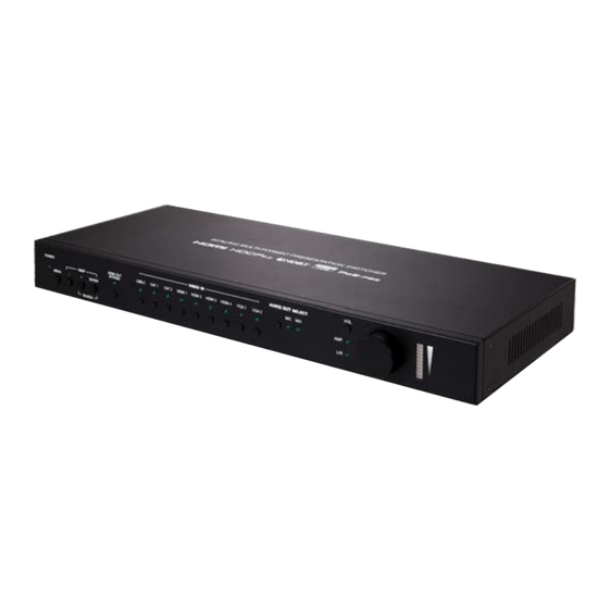
6. OPERATION CONTROLS AND FUNCTIONS 6.1 Front Panel VIDEO IN AUDIO OUT SELECT VOL. POWER HDMI OUT USB-C CAT 1 CAT 2 HDMI 1 HDMI 2 HDMI 3 HDMI 4 VGA 1 VGA 2 BYPASS 1080P AMP. MENU ENTER WUXGA POWER LED: This LED will illuminate to indicate the unit is on and receiving power. -
Page 10: Rear Panel
VOL. Button & LEDs: Press this button to select which audio output’s volume is controlled by the volume knob. When both LEDs are off, the knob controls the HDMI audio output (LPCM 2.0 only). VOL. Rotary Knob & LEDs: Rotating the knob increases or decreases the currently selected audio output’s volume level. - Page 11 RELAY 1~2 2-pin Terminal Blocks: Connect to devices that can be powered and controlled via a DC 0~24V/5A relay connection such as a curtain, projection screen, or lights. IR IN Port: Connect to an IR Extender to receive local IR control signals and extend them to devices connected to the other end of the HDBaseT connection.
- Page 12 VGA INPUT 1~2 Ports: Connect to VGA source equipment such as PCs or laptops. HDMI OUT Port: Connect to an HDMI TV, monitor, or amplifier for digital video and audio output. CAT5e/6/7 OUT Port: Connect to a compatible HDBaseT receiver with a single Cat.5e/6/7 cable for transmission of all data signals.
-
Page 13: Ir Cable Pinouts
6.3 IR Cable Pinouts IR Blaster IR Extender Cable Cable Power Infrared Infrared Power Not Used Ground 6.4 RS-232 Pinout and Defaults Serial Port Default Settings Baud Rate 19200 Data Bits Parity Bits None Stop Bits Flow Control None RS-232 Port 1 (Unit control) RS-232 Port 2 (HDBaseT extension) 4-pin Terminal Block 4-pin Terminal Block... -
Page 14: Osd Menu
6.5 OSD Menu All functions of this unit can be controlled by using the OSD (On Screen Display) which is activated by pressing the MENU button on the front of the unit. Use the + (PLUS), − (MINUS), and ENTER buttons to navigate the OSD menu. - Page 15 VIDEO 2ND LEVEL 3RD LEVEL 4TH LEVEL HDMI Out Bypass Output Route USB-C HDBT 1 HDBT 2 HDMI 1 HDMI 2 HDMI 3 HDMI 4 VGA 1 VGA 2 NATIVE HDMI Output Resolution Native HDBT 640x480@60 800x600@60 1024x768@60 1280x768@60 1360x768@60 1280x720@60 1280x800@60 1280x1024@60...
- Page 16 VIDEO 2ND LEVEL 3RD LEVEL 4TH LEVEL 720x480p 720x576p 1280x720p50 1280x720p60 1920x1080p24 1920x1080p25 1920x1080p30 1920x1080p50 1920x1080p60 3840x2160p24 3840x2160p25 3840x2160p30 3840x2160p50 3840x2160p60 3840x2160p50(420) 3840x2160p60(420) 4096x2160p24 4096x2160p25 4096x2160p30 4096x2160p50 4096x2160p60 4096x2160p50(420) 4096x2160p60(420) Aspect Over Scan Full BEST FIT Pan Scan Letterbox...
- Page 17 VIDEO 2ND LEVEL 3RD LEVEL 4TH LEVEL Under 1 Under 2 Follow In Blank Freeze Auto Setting Auto Sync Off Auto Input Auto Switch ENABLED HDCP Setting HDCP On USB-C Disabled ENABLED HDCP On HDBT 1 Disabled ENABLED HDCP On HDBT 2 Disabled ENABLED HDCP On HDMI 1...
- Page 18 1) HDMI Out Bypass: Enable or disable the video output bypass mode. When bypass is enabled, HDR video and bitstream audio can be supported, however it will disable the unit’s scaling and video adjustment functions. Note: This setting affects both the HDMI and HDBaseT outputs. This setting does not enable audio bypass.
- Page 19 PICTURE 2ND LEVEL 3RD LEVEL 4TH LEVEL 0~1023 (512) Color Gain R 0~1023 (512) Color Gain G 0~1023 (512) Color Gain B 0~1023 (512) Color Offset R 0~1023 (512) Color Offset G 0~1023 (512) Color Offset B 0~60 (30) Brightness 0~60 (30) Contrast 0~60 (30)
- Page 20 4) Fine Tune HDMI (Digital sources only): ■ Hue: Set the hue shift of the scaled output image. ■ Saturation: Set the color saturation level of the scaled output image. ■ Sharpness: Set the amount of sharpness processing to apply to the scaled output image.
- Page 21 AUDIO 2ND LEVEL 3RD LEVEL 4TH LEVEL Follow User Setting Audio On USB-C Analog 2 Analog 3 Analog 4 Analog 5 Analog 6 Audio On HDBT 1 [Same options as for USB-C] Audio On HDBT 2 [Same options as for USB-C] Audio On HDMI 1 [Same options as for USB-C]...
- Page 22 AUDIO 2ND LEVEL 3RD LEVEL 4TH LEVEL MIXER OFF Output Mixer Mixer On Mic Only 0~100 (0) Mic Gain 0~100 (85) HDMI Out Volume 0~100 (85) Analog Out Volume 0~100 (85) Speaker Out Volume HDMI Out Mute Analog Out Mute Speaker Out Mute 1) HDMI Out Bypass: Enable or disable HDMI audio bypass mode.
- Page 23 4) Output Mixer: Set the microphone mixing mode of the unit. ■ Mixer Off: Disable the audio mixer. ■ Mixer On: Enable the audio mixer. Audio from the current source and the microphone will be mixed together. ■ MIC Only: Output only the microphone audio source. This mode will override all other audio selections.
- Page 24 2ND LEVEL 3RD LEVEL 0~100 (50) H Position 0~100 (50) V Position 1~8 (1) Transparency OSD Menu Timeout INFO Display 1) H/V Position: Controls the position of the OSD menu. 2) Transparency: Set the transparency level of the OSD menu’s background.
- Page 25 ETHERNET 2ND LEVEL 3RD LEVEL 4TH LEVEL STATIC IP Mode DHCP 0~255 (192) Static IP Setting Static IP 0~255 (168) 0~255 (1) 0~255 (50) 0~255 (255) Mask 0~255 (255) 0~255 (0) 0~255 (0) 0~255 (192) Gate 0~255 (168) 0~255 (1) 0~255 (254) [Current IP address] [Unit’s MAC address]...
- Page 26 EDID 2ND LEVEL 3RD LEVEL DEFAULT FHD 2CH EDID On USB-C Default FHD MCh Default UHD 2Ch Default UHD MCh Default UHD+ 2Ch Default UHD+ MCh Default VGA User 1 User 2 Sink HDMI Sink HDBT EDID On HDBT 1 [Same options as for USB-C] EDID On HDBT 2 [Same options as for USB-C]...
- Page 27 EDID 2ND LEVEL 3RD LEVEL EDID On VGA 2 [Same options as for VGA 1] 1) EDID Selection: Select the EDID to use with each input. Note: In most cases, assigning a new EDID to an input will cause the affected input to briefly blink out while the source adapts to the new information.
- Page 28 FACTORY 2ND LEVEL 3RD LEVEL Reset All Execute FW Update From USB Exexute 1) Reset All: Selecting “Execute” will reset all of the unit’s settings back to their factory defaults. 2) FW Update From USB: Provides a way to update the unit’s firmware. Insert a USB thumb drive, with a valid firmware file (*.bin format) in the root directory, into the unit’s USB service port then select this option.
-
Page 29: Webgui Control
6.6 WebGUI Control • Device Discovery Please obtain the “Device Discovery” software from your authorized dealer and save it in a directory where you can easily find it. Connect the unit and your PC/Laptop to the same active network and execute the “Device Discovery” software. Click on “Find Devices on Network”... - Page 30 • WebGUI Overview After connecting to the WebGUI’s address in a web browser, the login screen will appear. Please enter the appropriate user name and password then click “Submit” to log in. Note: The default user name and password is “admin”. On the left side of the browser you will see the following menu tabs where all primary functions of the unit are controllable via the built in WebGUI.
-
Page 31: Video Tab
6.6.1 Video Tab This page provides video routing settings, I/O renaming options and control over the video output signal’s format and behavior. To begin assigning a new video route, please click an output button and then click on the button of the preferred input port. As you select each button they will change their color to orange. - Page 32 3) Additional Settings: ■ HDMI Out Bypass: Enable or disable the video output bypass mode. When bypass is enabled, HDR video and bitstream audio can be supported, however it will disable the unit’s scaling and video adjustment functions. Note: This setting affects both the HDMI and HDBaseT outputs. This setting does not enable audio bypass.
-
Page 33: Hdcp Tab
6.6.2 HDCP Tab Provides control over the HDCP behavior of each input. To enable or disable HDCP support on one or more inputs, select the preferred inputs on the left, and then select the HDCP mode on the right. The change will occur immediately. -
Page 34: Picture Tab
6.6.3 Picture Tab This tab provides controls over the scaled video output’s color, brightness, contrast. When a digital source is selected hue, saturation, sharpness and noise reduction are also controllable. When a VGA input is selected, the available controls will change and auto set, H/V position, clock and phase will become adjustable instead. - Page 35 ■ Saturation: Provides control over the color saturation level of the scaled output image. ■ Sharpness: Provides control over the amount of sharpness processing to apply to the scaled output image. ■ Noise Reduction: Provides control over the aggressiveness of the digital noise reduction processing when applied to the scaled output image.
-
Page 36: Audio Tab
6.6.4 Audio Tab This tab provides control over how audio is routed within the unit as well as control over audio mixing, individual output volume and the microphone’s gain level. 1) Audio Settings: ■ HDMI Volume & Mute: Set the volume level, or mute the audio, for the HDMI and HDBaseT audio outputs. - Page 37 ■ MIC Gain: Sets the microphone input’s volume level when the microphone is an active audio source (mixed or unmixed). ■ Output Mixer: Set the microphone mixing mode of the unit – Mixer Off: Disable the audio mixer. – Mixer On: Enable the audio mixer. Audio from the current source and the microphone will be mixed together.
-
Page 38: Osd Tab
6.6.5 OSD Tab This tab provides controls over the appearance of the unit’s informational OSD and OSD menu. 1) H/V Position: Controls the position of the OSD menu. 2) Transparency: Controls the transparency level of the OSD menu’s background. The available range is from Level 0 (fully opaque) to Level 8 (fully transparent). - Page 39 1) User EDID Settings: ■ Save Name: To change the name of a User EDID, type the new name in the space provided, then click on the “Save Name” button. ■ Download: To save an existing User EDID to your local PC please press the “Download”...
- Page 40 2) Sink EDID Download: To save the EDID from one of the connected displays to your local PC, select the appropriate sink from the dropdown list then press the “Download” button. Depending on your browser settings you will either be asked where to save the downloaded file, or the file will be transferred directly to the default download location on your PC.
-
Page 41: System Tab
6.6.7 System Tab Click on the “System” tab to make changes to various system settings. From this tab you can change the WebGUI login username and password as well as configure the RS-232/IR HDBaseT routing. Finally, this tab provides buttons to reset the unit to factory defaults and to update the firmware. - Page 42 3) Control Route Setting: These settings control the unit’s 2 relay ports as well as defining the HDBaseT routing to use for the RS-232 and IR ports on the unit. ■ Relay 1 & 2: Manually open or close Relay 1 and Relay 2. Selecting “ON”...
-
Page 43: Telnet Control
6.7 Telnet Control Before attempting to use Telnet control, please ensure that both the unit and the PC are connected to the same active networks. To Access the Command Line Interface (CLI) Click Start, type “cmd” in the search field, and Windows 7 press Enter. -
Page 44: Serial And Telnet Commands
6.8 Serial and Telnet Commands COMMAND Description and Parameters HELP Show the full command list. ? Show the full command list. HELP N1 Show details about the specified command. N1 = {Command name} GET MODEL NAME Show the unit’s model name. GET FW VER... - Page 45 COMMAND Description and Parameters GET IPADDR Show the unit’s current IP address. GET MAC ADDR Show the unit’s MAC address. SET STATIC IPADDR N1 Set the unit’s static IP address. N1 = X.X.X.X [X = 0 ~ 255, IP address] GET STATIC IPADDR...
- Page 46 COMMAND Description and Parameters GET WEBGUI PASSWORD Show the current WebGUI login password. GET IN PORT NUMBER Show the total number of inputs on the unit. GET OUT PORT NUMBER Show the total number of outputs on the unit. SET OUT A ROUTE N1 Route the specified input to both outputs.
- Page 47 COMMAND Description and Parameters GET IN N1 TIMING Show the index number of the current resolution detected on the specified input. Available values for N1: [USB-C input] [HDBaseT input 1] [HDBaseT input 2] [HDMI input 1] [HDMI input 2] [HDMI input 3] [HDMI input 4] [VGA input 1] [VGA input 2]...
- Page 48 COMMAND Description and Parameters [1280x720@60] [1280x800@60] [1280x1024@60] [1440x900@60] [1400x1050@60] [1680x1050@60] [1600x1200@60] [1920x1080@60] [1920x1200@60RB] [2560x1600@60RB] [720x480p] [720x576p] [1280x720p50] [1280x720p60] [1920x1080p24] [1920x1080p25] [1920x1080p30] [1920x1080p50] [1920x1080p60] [3840x2160p24] [3840x2160p25] [3840x2160p30] [3840x2160p50] [3840x2160p60] [3840x2160p50(4:2:0)] [3840x2160p60(4:2:0)] [4096x2160p24] [4096x2160p25] [4096x2160p30] [4096x2160p50] [4096x2160p60] [4096x2160p50(4:2:0)] [4096x2160p60(4:2:0)] GET OUT A TIMING Show the index number of the current resolution used by both outputs.
- Page 49 COMMAND Description and Parameters GET IN SOURCE LIST List the port type of all inputs on the unit. GET OUT TIMING LIST List all available output resolutions with their local index numbers. SET OUT A CONTRAST N1 Set the scaled output’s contrast level. N1 = 0~60 [Contrast level] GET OUT A CONTRAST...
- Page 50 COMMAND Description and Parameters GET OUT A SHARPNESS Show the sharpness level when the output is scaled. SET OUT A NR N1 Set the amount of noise reduction to apply when the output is scaled. Available values for N1: [Off] [Low] [Middle] [High]...
- Page 51 COMMAND Description and Parameters SET OUT A ASPECT RATIO N1 Set the aspect ratio of the video shown when the output is scaled. Available values for N1: [Overscan] [Full] [Best fit] [Pan & scan] [Letterbox] [Underscan 1] [Underscan 2] [Follow input] GET OUT A ASPECT RATIO...
- Page 52 COMMAND Description and Parameters SET OUT A G GAIN N1 Set the scaled output’s green gain level. N1 = 0~1023 [Green gain level] GET OUT A G GAIN Show the scaled output’s current green gain level. SET OUT A B GAIN N1 Set the scaled output’s blue gain level.
- Page 53 COMMAND Description and Parameters SET IN N1 PHASE N2 Set the PC phase value for the specified input (VGA inputs only). Available values for N1: [VGA input 1] [VGA input 2] N2 = 0~255 [PC phase] GET IN N1 PHASE Show the current PC phase value for the specified input (VGA inputs only).
- Page 54 COMMAND Description and Parameters GET IN N1 HPOSITION Show the current PC horizontal position for the specified input (VGA inputs only). Available values for N1: [VGA input 1] [VGA input 2] SET IN N1 VPOSITION N2 Set the PC vertical position for the specified input (VGA inputs only).
- Page 55 COMMAND Description and Parameters SET OUT A BLANK N1 Enable or disable blanking the video output Available values for N1: [Video output normal] [Video output blanked] GET OUT A BLANK Show the current video output blanking state. SET OUT A FREEZE N1 Enable or disable freezing the video output.
- Page 56 COMMAND Description and Parameters SET OUT A OSD VPOSITION N1 Set the vertical position of the OSD menu. N1 = 0~100 [Vertical position] GET OUT A OSD VPOSITION Show the current vertical position of the OSD menu. SET OUT A OSD HPOSITION N1 Set the horizontal position of the OSD menu.
- Page 57 COMMAND Description and Parameters SET AUDIO OUT N1 MUTE N2 Enable or disable muting the specified audio output. Available values for N1: [HDMI audio output] [HDBaseT audio output] [Standard analog audio output] [Amplified analog audio output] Available values for N2: [Mute disabled] [Mute enabled] Note: The HDMI and HDBaseT outputs share their settings.
- Page 58 COMMAND Description and Parameters GET AUDIO OUT A ROUTE Show the unit’s current audio source selection behavior. SET AUDIO OUT N1 VOLUME N2 Set the volume level of the specified output’s audio. Available values for N1: [HDMI audio output] [HDBaseT audio output] [Standard analog audio output] [Amplified analog audio output] N2 = 0~100...
- Page 59 COMMAND Description and Parameters SET HDMI OUT AUDIO BYPASS N1 Enable or disable the HDMI/HDBaseT audio output bypass mode. Available values for N1: [Audio bypass disabled] [Audio bypass enabled] GET HDMI OUT AUDIO BYPASS Show the current HDMI/HDBaseT audio output bypass mode state.
- Page 60 COMMAND Description and Parameters GET VIDEO IN N1 AUDIO ROUTE Show the audio source currently assigned to the specified video input to be used when Follow User Mode is enabled. Available values for N1: [USB-C input] [HDBaseT input 1] [HDBaseT input 2] [HDMI input 1] [HDMI input 2] [HDMI input 3]...
- Page 61 COMMAND Description and Parameters Available values for N2: [Default FHD 2CH] [Default FHD MCH] [Default UHD 2CH] [Default UHD MCH] [Default UHD+ 2CH] [Default UHD+ MCH] [Default VGA] [User EDID 1] [User EDID 2] [HDMI sink] [HDBaseT sink] GET IN N1 EDID Show the EDID currently being used on the specified input.
- Page 62 COMMAND Description and Parameters SET IN N1 HDCP MODE N2 Set the HDCP behavior of the specified input. Available values for N1: [USB-C input] [HDBaseT input 1] [HDBaseT input 2] [HDMI input 1] [HDMI input 2] [HDMI input 3] [HDMI input 4] Available values for N2: [HDCP support disabled] [HDCP support enabled]...
- Page 63 COMMAND Description and Parameters Possible response values: [No HDCP] [HDCP 1.x] [HDCP 2.2] GET OUT N1 HDCP STATUS Show the current HDCP status of the specified output. Available values for N1: [HDMI output] [HDBaseT output] Possible response values: [No HDCP] [HDCP 1.x] [HDCP 2.2] [HDCP 1.x failed]...
- Page 64 COMMAND Description and Parameters SET IR N1 Set the HDBaseT routing path for the unit’s IR ports. Available values for N1: [HDBaseT Out] [HDBaseT Input 1] [HDBaseT Input 2] GET IR Show the current HDBaseT routing path for the unit’s IR ports. Note: Commands will not be executed unless followed by a carriage return.
-
Page 65: Connection Diagram
7. CONNECTION DIAGRAM Display Display Source Source Screen Volume Screen Volume Down Down 1.5m CD Player Powered 60° 60° Speakers Microphone IR Input Input IR Output Router RS-232 Power Supply MIC IN ANALOG AUDIO AUDIO OUT L+ L- R+ R- RELAY IR IN IR OUT... -
Page 66: Specifications
8. SPECIFICATIONS 8.1 Technical Specifications HDMI Bandwidth 18Gbps USB-C Bandwidth 21.6Gbps VGA Bandwidth 165MHz HDBaseT Bandwidth 10.2Gbps Input Ports 1×USB (Type-C) 2×HDBaseT (RJ-45) 4×HDMI (Type-A) 2×VGA (HD-15) 6×Stereo Audio (3.5mm) 1×Microphone (6.35mm) Output Ports 1×HDMI (Type-A) 1×HDBaseT (RJ-45) 1×Stereo Audio (5-pin Terminal Block) 1×Stereo Audio (2×2-pin Term. - Page 67 Dimensions (W×H×D) 432mm×43mm×164mm [Case Only] 432mm×43mm×174mm [All Inclusive] Weight 2547g Chassis Material Metal (Steel) Chassis Color Black Operating Temperature 0˚C – 40˚C/32˚F – 104˚F Storage Temperature -20˚C – 60˚C/-4˚F – 140˚F Relative Humidity 20 – 90% RH (Non-condensing) Power Consumption 53.966W...
-
Page 68: Video Specifications
8.2 Video Specifications 8.2.1 Bypass Output Bypass Input Output Supported Resolutions (Hz) HDMI HDBT USBC HDMI HDBT 720×400p@70/85 640×480p@60/72/75/85 720×480i@60 720×480p@60 ... - Page 69 Bypass Input Output Supported Resolutions (Hz) HDMI HDBT USBC HDMI HDBT 1920×1080p@50/60 1920×1200p@60RB 2560×1440p@60RB 2560×1600p@60RB 2048×1080p@24/25/30 ...
-
Page 70: Scaled Output
8.2.2 Scaled Output Scaled Output Supported Resolutions (Hz) HDMI HDBT 720×400p@70/85 640×480p@60/72/75/85 720×480i@60 720×480p@60 720×576i@50 720×576p@50 800×600p@56/60/72/75/85 848×480p@60 1024×768p@60/70/75/85 1152×864p@75 1280×720p@50/60 1280×768p@60/75/85 1280×800p@60/75/85 1280×960p@60/85 ... - Page 71 Scaled Output Supported Resolutions (Hz) HDMI HDBT 2560×1600p@60RB 2048×1080p@24/25/30 2048×1080p@50/60 3840×2160p@24/25/30 3840×2160p@50/60 (4:2:0) 3840×2160p@24, HDR10 3840×2160p@50/60 (4:2:0), HDR10 3840×2160p@50/60 4096×2160p@24/25/30 4096×2160p@50/60 (4:2:0) ...
-
Page 72: Audio Specifications
8.3 Audio Specifications 8.3.1 Digital Audio HDMI Input / Output LPCM Max Channels 2 Channels (8 Channels in bypass) Sampling Rate (kHz) 32, 44.1, 48, 88.2, 96, 176.4, 192 Bitstream (Bypass Only) Supported Formats Standard & High-Definition HDBaseT Input / Output LPCM Max Channels 2 Channels (8 Channels in bypass) -
Page 73: Analog Audio
8.3.2 Analog Audio Analog Input (3.5mm) Max Audio Level 1Vrms Impedance 10kΩ Type Unbalanced Mic Input Max Audio Level 50Vrms Impedance 6.8kΩ Type Unbalanced Analog Output (5-pin Terminal Block) Max Audio Level 4Vrms THD+N < −84dB@0dBFS 1kHz (A-wt) > 104dB@0dBFS Frequency Response <... -
Page 74: Cable Specifications
8.4 Cable Specifications 1080p 4K30 4K60 (4:4:4) (4:4:4) Cable Length 8-bit 12-bit 8-bit 8-bit High Speed HDMI Cable HDMI Input HDMI Output USB-C Cable USB-C Input VGA Cable VGA Input Ethernet Cable Cat.5e/6 100m Cat.6A/7 100m 100m Bandwidth Category Examples: •... -
Page 75: Hdbaset Features
8.5 HDBaseT Features HDBaseT Feature Set Transmitter Video & Audio Extension Supported LAN Extension Supported Send power to Receiver Supported (PoH) Accept power from Receiver Unsupported IR Extension Supported RS-232 Extension Supported USB 2.0 Extension Unsupported HDBaseT Feature Set Receiver Video &... -
Page 76: Acronyms
9. ACRONYMS ACRONYM COMPLETE TERM Analog-to-Digital Converter ASCII American Standard Code for Information Interchange Cat.5e Enhanced Category 5 cable Cat.6 Category 6 cable Cat.6A Augmented Category 6 cable Cat.7 Category 7 cable Command-Line Interface Digital-to-Analog Converter Decibel DHCP Dynamic Host Configuration Protocol Digital Visual Interface EDID Extended Display Identification Data... - Page 77 ACRONYM COMPLETE TERM Media Access Control Megahertz On-Screen Display Powered Device Power over HDBaseT Power Sourcing Equipment Signal-to-Noise Ratio Transmission Control Protocol THD+N Total Harmonic Distortion plus Noise TMDS Transition-Minimized Differential Signaling Ultra-High-Definition (10.2Gbps) Ultra-High-Definition Plus (18Gbps) UHDTV Ultra-High-Definition Television Universal Serial Bus Video Graphics Array WUXGA (RB)
- Page 80 CYPRESS TECHNOLOGY CO., LTD Home page: http://www.cypress.com.tw...
Need help?
Do you have a question about the CSC-6030HB and is the answer not in the manual?
Questions and answers