Table of Contents
Advertisement
Quick Links
W
att
Electric Power Meter - Installation Manual
WattNode BACnet
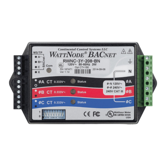
WNC-3Y-208-BN
WNC-3Y-400-BN
WNC-3Y-480-BN
WNC-3Y-600-BN
WNC-3D-240-BN
WNC-3D-400-BN
WNC-3D-480-BN
N
ode
Models
www.ctlsys.com
BaC
®
WattNode Revenue
for BACnet Models
RWNC-3Y-208-BN
RWNC-3Y-400-BN
RWNC-3Y-480-BN
RWNC-3Y-600-BN
RWNC-3D-240-BN
RWNC-3D-400-BN
RWNC-3D-480-BN
Net
®
Advertisement
Table of Contents

Related Manuals for socomec CCS WattNode BACnet WNC-3Y-208-BN


Summary of Contents for socomec CCS WattNode BACnet WNC-3Y-208-BN
- Page 1 ® ® Electric Power Meter - Installation Manual WattNode BACnet WattNode Revenue Models for BACnet Models WNC-3Y-208-BN RWNC-3Y-208-BN WNC-3Y-400-BN RWNC-3Y-400-BN WNC-3Y-480-BN RWNC-3Y-480-BN WNC-3Y-600-BN RWNC-3Y-600-BN WNC-3D-240-BN RWNC-3D-240-BN WNC-3D-400-BN RWNC-3D-400-BN WNC-3D-480-BN RWNC-3D-480-BN www.ctlsys.com...
-
Page 2: Table Of Contents
Contents Precautions ..........................3 Symbols .............................3 Overview ...........................3 Additional Literature ........................3 Electrical Service Types ......................4 Installation ..........................7 Installation Checklist ........................7 Mounting ............................7 Connect Voltage Terminals ......................7 Connect Current Transformers ....................8 Connect the Output Signals .......................9 Connect Thermistor .........................10 Operation ..........................10 Initial Configuration ........................10 Power Status LEDs ........................10 Communication LED ........................12 Monitoring ..........................12... -
Page 3: Precautions
1 Precautions 1.1 Only qualified personnel or licensed electricians should install the WattNode meter. The mains voltages of 120 to 600 Vac can be lethal! 1.2 Follow all applicable local and national electrical and safety codes. 1.3 The terminal block screws are not insulated. Do not contact metal tools to the screw terminals if the circuit is live! 1.4 Verify that circuit voltages and currents are within the proper range for the meter model. -
Page 4: Electrical Service Types
Continental Control Systems LLC PC or BACnet Host ® A−, D0, RxD−/TxD− Ground WNC- 3Y-xxx B+, D1, RxD+/TxD+ WNC- 3D-xxx Common ØA ØA CT Status WHITE ØB ØB CT Status BLACK ØC ØC CT Status Source Faces Phase A Phase B Phase C Current Transformers... - Page 5 Table 1 above lists the WattNode models and common circuit types. In the “Electrical Service Types” column, when two voltages are listed with a slash between them, they indicate the line-to- neutral / line-to-line voltages. The “Line-to-Neutral” and “Line-to-Line” columns show the operating ranges for the WattNode meters.
- Page 6 ® Ø Ø Ø Ø Ø Ø Earth 2.2.5 Three-Phase Four-Wire Wye with Neutral This is a common commercial and industrial service. ® Ø Ø Ø Ø Ø Ø Earth Neutral 2.2.6 Three-Phase Four-Wire Delta with Neutral (Wild Leg) The uncommon four-wire delta electrical service is a three-phase delta service with a center-tap on one of the transformer windings to create a neutral for single-phase loads.
-
Page 7: Installation
3 Installation 3.1 Installation Checklist See the sections referenced below for installation details. □ Turn off power before making line voltage connections. □ Mount the WattNode meter (see 3.2). □ Connect circuit breakers or fuses and disconnects (see 3.3.1). □ Connect the line voltage wires to the meter’s green terminal block (see 3.3.2). -
Page 8: Connect Current Transformers
3.3.2 Line Wiring ● Always turn off power before connecting the line voltage inputs to the meter. ● For the line voltage wires, CCS recommends 16 to 12 AWG stranded wire, type THHN, MTW, or THWN, 600 V. ● Do not place more than one voltage wire in a screw terminal; use separate wire nuts or termi- nal blocks if needed. -
Page 9: Connect The Output Signals
Install the CTs around the conductor to be measured and connect the CT leads to the meter. Al- ways turn off power before disconnecting any live conductors. Split-core CTs can be opened for installation around a conductor. A nylon cable tie may be se- cured around the CT to prevent inadvertent opening. -
Page 10: Connect Thermistor
3.5.2 Connect RS-485 A - B+ C ● RS-485 wiring can be complex when multiple devices are connected, when running wires for long distances, and when using termination and biasing resistors. If you have any questions, consult the Operating and Reference Guide. - Page 11 Yellow Green Yellow Green Yellow Green 1.0sec 1.0sec 1.0sec 4.2.2 Positive Power Any phase with the LEDs flashing green is indicating normal positive power. Green Off Green Off Green Off 4.2.3 No Power Any phase with a solid green LED indicates no power, but line voltage is present. Green 4.2.4 No Voltage Any phase LED that is off indicates no voltage on that phase.
-
Page 12: Communication Led
For other LED patterns, see the Operating and Reference Guide or contact support for assis- tance. 4.3 Communication LED Near the upper left corner, there is a diagnostic Com (communication) LED that can indicate the following: ● Green Off A short green flash indicates a valid packet addressed to this device. -
Page 13: Measurement
For accuracy at other conditions, see the reference guide. WattNode Revenue Models: ● Meets the ANSI C12.1-2008 standard for revenue metering when used with IEEE C57.13 class 0.6 current transformers. Includes a certificate of calibration. 5.2 Measurement Update Rate: 1.0 second. Internally, all measurements are performed at this rate. Start-Up Time: ~1.3 second. -
Page 14: Thermistor Input
Maximum Power Supply Voltage Range: -20% to +15% of nominal (see table above). For the 3D-240 service, this is -20% of 208 Vac (166 Vac) to +15% of 240 Vac (276 Vac). Operating Frequencies: 50/60 Hz Measurement Category: CAT III Measurement category III is for measurements performed in the building installation or on the load side of the main service breaker. -
Page 15: Certifications
5.6 Certifications Safety: ● UL 61010-1 (3rd Edition) ● CAN/CSA-C22.2 No. 61010-1-04 ● IEC 61010-1:2010 (3rd Edition) Immunity: EN 61326: 2002 (Industrial Locations) Electrostatic Discharge: EN 61000-4-2 Radiated RF Immunity: EN 61000-4-3 Electrical Fast Transient / Burst: EN 61000-4-4 Surge Immunity: EN 61000-4-5 Conducted RF Immunity: EN 61000-4-6 Voltage Dips, Interrupts: EN 61000-4-11 Emissions:... -
Page 16: Warranty
5.10 Warranty All products sold by Continental Control Systems, LLC (CCS) are guaranteed against defects in material and workmanship for a period of five years from the original date of shipment. CCS’s responsibility is limited to repair, replacement, or refund, any of which may be selected by CCS at its sole discretion.
Need help?
Do you have a question about the CCS WattNode BACnet WNC-3Y-208-BN and is the answer not in the manual?
Questions and answers