
Related Manuals for socomec DIRIS B-10


Summary of Contents for socomec DIRIS B-10
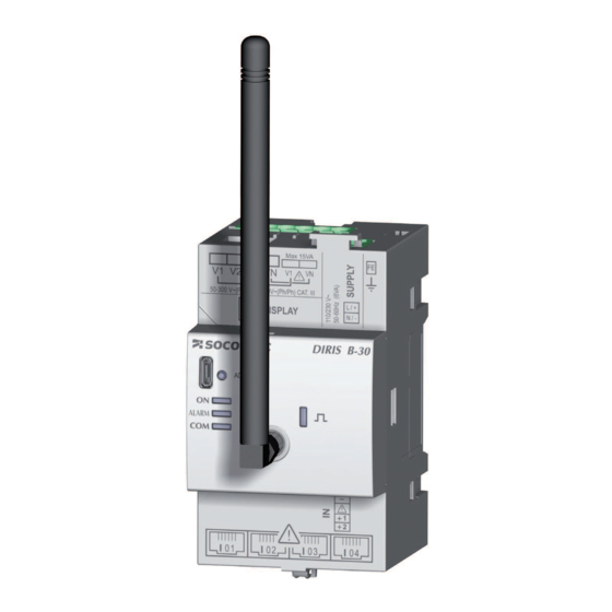
- Page 1 DIRIS B-10 & B-30 Multifunction meters and associated current sensors www.socomec.com/ en/diris-b...
-
Page 2: Table Of Contents
6.3.1. Connection concept ........6.3.2. Details of the RJ12 connections for each current sensor ..DIRIS B - 546 770 A - SOCOMEC... - Page 3 12.2. Evaluation of the power supply quality ......DIRIS B 546 770 A - SOCOMEC...
-
Page 4: Documentation
1. DOCUMENTATION sensors is available on the SOCOMEC website at the following address: www.socomec.com/en/diris-b DIRIS B - 546 770 A - SOCOMEC... -
Page 5: Hazards And Warnings
2. HAZARDS AND WARNINGS professionals. SOCOMEC shall not be held responsible for failure to comply with the instructions in this manual. 2.1. Risk of electrocution, burns or explosion Caution: risk of electric shock Ref. ISO 7000-0434B (2004-01) Caution Refer to the accompanying documentation each time this Ref. -
Page 6: Liability
The unit must be positioned within an installation which complies with the standards currently in force. Any cables which need to be replaced may only be replaced with cables with the correct ratings. DIRIS B - 546 770 A - SOCOMEC... -
Page 7: Preliminary Operations
3. PRELIMINARY OPERATIONS installation. The packaging is in good condition The unit has not been damaged during transportation The device reference conforms to your order DIRIS B 546 770 A - SOCOMEC... -
Page 8: Introduction
*PMD: Performance Measuring and Monitoring Device in accordance with IEC 61557-12. 4.1.1. Range DIRIS B-10 DIRIS B-30 RS DIRIS B-30 RF Communication RS485 Ref. 4829 0010 Accessories Cable for remote antenna. Sealing kit. USB cable for configuration Height: 210mm 4.1.2. Functions DIRIS B - 546 770 A - SOCOMEC... - Page 9 - Connects to a DIRIS D-30 remote display via RJ9 or D-50 / D-70 via RS485 - Time synchronisation with the gateway - Auto-addressing in association with the gateway (*) Available only on the DIRIS B-30 RS (ref. 4829 0000) and DIRIS B-30 RF (ref. 4829 0002) DIRIS B 546 770 A - SOCOMEC...
-
Page 10: Electrical Values Measured
THD system Phase to neutral voltage harmonics orders 1 to 63 Phase to phase voltage harmonics orders 1 to 63 Current harmonics orders 1 to 63 Crest Factor Energies Total energy Partial energy DIRIS B - 546 770 A - SOCOMEC... -
Page 11: Dimensions
4.1.4. Dimensions Dimensions in/mm DIRIS G-40 / G-60 RF 1.73 0.59 1.42 2.12 2.56 DIRIS B 546 770 A - SOCOMEC... -
Page 12: Presentation Of Optional Modules
4.2.2. Dimensions Dimensions in/mm 1.73 0.59 2.56 DIRIS O-iod DIRIS O-ioa DIRIS O-it DIRIS O-m DIRIS O-p DIRIS O-b/ip DIRIS O-b/mstp 1.77in / 45mm 2.12in / 54mm DIRIS B - 546 770 A - SOCOMEC... -
Page 13: Presentation Of Associated Current Sensors
4829 0602 4829 0603 4829 0601 4829 0580 4829 0581 4829 0582 4829 0595 4829 0583 4829 0584 4829 0596 4829 0588 4829 0589 4829 0590 4829 0591 4829 0592 4829 0597 4829 0593 4829 0594 DIRIS B 546 770 A - SOCOMEC... -
Page 14: Te Solid-Core Current Sensors
4829 0500 4829 0501 4829 0502 4829 0503 4829 0504 4829 0505 Reference TE-90 Pitch 90 mm Nominal current range In Actual 12 - 2400 A range Maximum l 4829 0506 Reference DIRIS B - 546 770 A - SOCOMEC... - Page 15 13.5 x 13.5 21 x 21 31 x 31 41 x 41 0.69 0.69 0.77 0.85 17.5 17.5 19.5 21.5 3.54 0.08 0.97 24.6 2.52 / 64 0.77 19.7 1.42 TE-90 Dimensions in/mm DIRIS B 546 770 A - SOCOMEC...
-
Page 16: Tr Split-Core Current Sensors
30 x 42 x 74 45 x 44 x 95 57 x 42 x 111 0.39 0.63 0.94 1.42 2.28 2.40 2.83 3.23 0.57 0.75 0.87 0.87 14.5 1.02 1.22 1.34 1.59 40.5 DIRIS B - 546 770 A - SOCOMEC... -
Page 17: Tf Flexible Current Sensors
32 - 7200 A range Reference 4829 0570 4829 0571 4829 0572 4.3.3.2. Dimensions Ø Ø 0.71 0.71 1.49 TF-55 TF-120 TF-300 Dimensions in/mm 2.16 4.72 11.81 Diameter 7.16 14.80 37.08 0.23 0.43 0.43 59.05 1500 DIRIS B 546 770 A - SOCOMEC... -
Page 18: Adapters For 5A Sensors
4.3.4.1. Range 5A adapter I nom. I max. 4829 0599 Reference 4.3.4.2. Dimensions 5A adapter Dimensions in/mm 1.10 x 0.79 x 1.77 LxHxD 28 x 20 x 45 Aperture ø 0.33 ø 8.4 DIRIS B - 546 770 A - SOCOMEC... -
Page 19: Mounting
5.2. Installing the DIRIS B 5.2.1. DIN rail mounting Mounting Removal 1.38 0.29 or 0.59 7.5 or 15 5.2.2. Plate mounting Type of screw: M4 Tightening torque: 0.5 Nm Washer: maximum diameter 0.47in/12mm DIRIS B 546 770 A - SOCOMEC... -
Page 20: Sealing Accessory For Sensors
5.2.3. Sealing accessory for sensors Sealing case for terminal Reference 4829 0600 5.3. Installing the optional modules 5.3.1. Optional module 5.3.2. Installing an optional module on an optional module Optional module Optional module Optional module DIRIS B - 546 770 A - SOCOMEC... -
Page 21: Installing Te Solid-Core Sensors
4829 0501 TE-25 25 mm 4829 0502 TE-35 35 mm 4829 0503 TE-45 45 mm 4829 0504 TE-55 55 mm 4829 0505 TE-90 90 mm 4829 0506 5.4.2. DIN rail mounting TE-18 -> TE-55 DIRIS B 546 770 A - SOCOMEC... - Page 22 NB: Install sensor TE-90 to the DIN rail to make it easier to install. This is a temporary installation. Use the clamps to install the TE-90 sensors on the DIN rail. DIRIS B - 546 770 A - SOCOMEC...
-
Page 23: Plate Mounting
5.4.3. Plate mounting TE-18 0.17 / 1.05 26.8 0.81 20.5 TE-25 - > TE-55 0.20 DIRIS B 546 770 A - SOCOMEC... - Page 24 TE-90 Removing clamps diameter 0.20 diameter 5.2 NB: Use the clamps to install the TE-90 sensors on the board. DIRIS B - 546 770 A - SOCOMEC...
-
Page 25: Installing On A Cable With Clamping Collar
TE-90 Removing clamps NB: Use the clamps to install the TE-90 sensors on a cable with clamping collar. Do NOT clamp or pull out NON-INSULATED conductors carrying DANGEROUS VOLTAGE which Ref. IEC 61010-2-032 DIRIS B 546 770 A - SOCOMEC... -
Page 26: Bar Mounting
The jaws must be per- pendicular to the holding notches. Do NOT clamp or pull out NON-INSULATED conductors carrying DANGEROUS VOLTAGE which Ref. IEC 61010-2-032 DIRIS B - 546 770 A - SOCOMEC... -
Page 27: Sensors Assembly
Mounting accessories for sensor combination: Linear assembly Staggered assembly Reference 4829 0598 These accessories must be ordered separately. 5.4.7. Sealing accessories for sensors Sealing case for terminal Reference 4829 0600 These accessories must be ordered separately. DIRIS B 546 770 A - SOCOMEC... -
Page 28: Installing Tr Split-Core Sensors
Do NOT clamp or pull out NON-INSULATED conductors carrying DANGEROUS VOLTAGE which Ref. IEC 61010-2-032 5.6. stranded sensors TE mounting 5.6.1. Installing the casing DIN rail Plate Chassis 0.19 0.29 or 0.59 7.5 or 15 1.38 Washer max. DIRIS B - 546 770 A - SOCOMEC... -
Page 29: Cable Mounting
DANGEROUS VOLTAGE which could cause Ref. IEC 61010-2-032 Click! 5.7. Installing the 5A adapter 5A secondary current transformer Do NOT clamp or pull out NON-INSULATED conductors carrying DANGEROUS VOLTAGE which Ref. IEC 61010-2-032 DIRIS B 546 770 A - SOCOMEC... -
Page 30: Connection
(ref. 4829 0000 / 4829 0010) solid 0.14 mm -> 1.5 mm stranded 0.14 mm -> 1.5 mm solid 0.14 mm -> 1.5 mm 7 mm stranded 0.14 mm strand -> 1.5 mm 7 mm DIRIS B - 546 770 A - SOCOMEC... - Page 31 (Self-powered and data) 10-30 VDC 12 VDC I 04 I 04 I 01 Power supply of optional modules 110-230VAC OPTIONAL MODULE 4 OPTIONAL MODULE 3 OPTIONAL MODULE 2 OPTIONAL MODULE 1 DIRIS B DIRIS B 546 770 A - SOCOMEC...
-
Page 32: Connecting The Optional Modules
-> 1.5 mm stranded Length max. 3 m 7 mm PT100 or PT1000 Power supply of optional modules DIRIS O-iod and O-ioa DIRIS O-iod DIRIS O-ioa DIRIS O-it INPUT INPUT OUTPUT OUTPUT DIRIS B - 546 770 A - SOCOMEC... -
Page 33: Communication Modules
BACnet/IP communication communicationmodule module RJ45 0.2 mm -> 2.5 mm solid 0.2 mm -> 2.5 mm stranded 7 mm BACnet/IP BACnet MS/TP DIRIS O-m RS485 DIRIS O-p DIRIS O-b/ip DIRIS O-b/mstp SUBD 9 DIRIS B 546 770 A - SOCOMEC... -
Page 34: Connecting The Current Sensors
SOCOMEC cable for DIRIS B current sensors DIRIS Digiware Click! Click! Click! SOCOMEC SOCOMEC cable for cable for current sensors DIRIS B current sensors current s DIRIS Digiware DIRIS B DIRIS Digiware DIRIS B - 546 770 A - SOCOMEC... -
Page 35: Connecting To The Electrical Network And Loads
6.3.3. Connecting to the electrical network and loads simultaneously. SOCOMEC cables must be used for the current sensors. 6.3.3.1. installation. Network type Configurable load 1P+N 2P+N 3P+N 6.3.3.2. Description of the main network and load combinations Legend: 3P+N – 4CT... - Page 36 3P – 2CT (x2) 3P – 1CT (x4) (4 three-phase balanced loads) V1 V2 V3 VN V1 V2 V3 VN Fuse: 0.5 A gG / BS 88 2A gG / 0.5 A class CC DIRIS B - 546 770 A - SOCOMEC...
-
Page 37: Connection Of The Functional Earth
It is recommended that the functional earth is connected to guarantee optimum measuring accuracy and better emissivity/immunity for the electromagnetic compatibility (class B in conducted emission). Earth must not be used in a neutral IT system. DIRIS B 546 770 A - SOCOMEC... -
Page 38: Status And Auto-Addressing Leds
PMD (DIRIS A) and meters (COUNTIS). Two modes are available: Mode 1 - Auto-detection and automatic addressing Mode 2 - Auto-detection and address selection Mode 1 is without external equipment (see description below). DIRIS B - 546 770 A - SOCOMEC... - Page 39 DIRIS G DIRIS B RS485 / DIRIS B RF Press 3 sec. RS485 or RS485 or Press Press 3 sec. 3 sec. Press 3 sec. exchange of data is possible at this time DIRIS B 546 770 A - SOCOMEC...
-
Page 40: Communication
COUNTIS 8.2. RS485 rules RS485 communication is available on the DIRIS B-10 (ref. 4829 0010) and DIRIS B-30 RF (ref. 4829 0000). It is or gateway. The Modbus protocol requires a dialogue with a master/slave structure. The mode of communication is the RTU... -
Page 41: Radio-Frequency (Rf) Rules
DIRIS G-40 and G-60 gateways in the RS485/RF version and will be seen as Modbus RTU slaves by these gateways. protocol. The WEBVIEW web server embedded in the gateway offers advanced data Monitoring and Reporting functions (refer to the corresponding manual for more details). DIRIS B 546 770 A - SOCOMEC... -
Page 42: Ec Declaration Of Conformity
The communication tables and associated explanations can be found on the documentations page for the DIRIS B on the SOCOMEC website at the following address: www.socomec.com/en/diris-b The communication tables are sent via Modbus. DIRIS B - 546 770 A - SOCOMEC... -
Page 43: Configuration
9.1.1. Connection modes Easy USB cable for RS485 Easy RS485 RS485 RS485 DIRIS DIRIS B DIRIS G DIRIS Digiware C-31 COUNTIS RS485 Easy RS485 DIRIS DIRIS B DIRIS Digiware D-50 / D-70 COUNTIS RS485 DIRIS B 546 770 A - SOCOMEC... - Page 44 Easy Ethernet RS485 RS485 RS485 DIRIS DIRIS B DIRIS G DIRIS Digiware C-31 COUNTIS RS485 Easy Ethernet RS485 DIRIS DIRIS B DIRIS Digiware D-50 / D-70 COUNTIS RS485 DIRIS B - 546 770 A - SOCOMEC...
-
Page 45: Using Easy Config
9.1.2. successive steps: Network —> Loads —> Measurement method —> Values to be stored —> Alarms —> (2). For each setting selected transformer is used. DIRIS B 546 770 A - SOCOMEC... - Page 46 Calculation method Alarms details. DIRIS B - 546 770 A - SOCOMEC...
-
Page 47: Synchronisation Of Products
9.1.3. Synchronisation of products DIRIS B 546 770 A - SOCOMEC... -
Page 48: Configuration From The Diris D-30 Remote Display
9.2.1. Connection mode Display Refer to the manual for the DIRIS D-30 display for more details. Connection cables for the remote display (RJ9): Length (m) Quantity Reference 4829 0280 4829 0281 length. DIRIS B - 546 770 A - SOCOMEC... -
Page 49: Alarms
- On one phase of the three phases: Phase1 or Phase2 or Phase3 10.1.2. Voltage and current unbalance (in a three-phase network) Selection of the hysteresis and high/low threshold Setting a time delay at the start and end of the alarm DIRIS B 546 770 A - SOCOMEC... -
Page 50: En 50160 Voltage Quality Events
Alarm upon change of status for a digital input Choice of a rising or falling edge Setting a time delay at the start and end of the alarm 10.1.7. Combination of alarms DIRIS B - 546 770 A - SOCOMEC... -
Page 51: Setup Alarms
Fixed: Alarm upon event (takes priority if there is a commissioning alarm at the same time) 10.3.2. Activation of an output 10.3.3. Activation of an input taken into account if the alarm is complete DIRIS B 546 770 A - SOCOMEC... -
Page 52: Rs485 Modbus
10.3.4. RS485 Modbus Information on the alarms with timestamping available via the RS485 communication bus Sends alarm acknowledgement 10.3.5. Information on the alarms with timestamping Sends alarm acknowledgement DIRIS B - 546 770 A - SOCOMEC... -
Page 53: Features
Class 1 with TR sensors Voltage measurement Characteristics of the network measured Frequency range 45 - 65Hz Frequency accuracy Class 0.02 Network type Single-phase/ Two-phase / Two-phase with neutral / Three-phase / Three- phase with neutral DIRIS B 546 770 A - SOCOMEC... -
Page 54: Communication Specifications
Storage temperature Operating humidity Operating altitude Vibration Rated impulse voltage IEC 60947-1 V. IMP: 6.4kV PEP ecopassport - ISO 14025 Impact resistance Front panel: 5J - casing: 1J (IEC 61010-1 Ed 3.0) DIRIS B - 546 770 A - SOCOMEC... -
Page 55: Electromagnetic Compatibility
2 per optional module - 4 optional modules max. Type polarisation Function Logic status or pulse meter Input connection Number of outputs Type Function controlled status Output connections UL 61010-1 conformity DIRIS O-ioa - 2 analogue inputs/2 analogue outputs DIRIS B 546 770 A - SOCOMEC... - Page 56 BACnet IP communication Connection RJ45 port DIRIS O-b/mstp - BACnet MSTP communication Connection RS485 Protocol BACnet MSTP Baudrate 9600 - 76800 bauds Start-up time 1 min 15 s Function BACnet MSTP communication Connection DIRIS B - 546 770 A - SOCOMEC...
-
Page 57: Diris D-30 Display Characteristics
11.3.2. Single product connection Self-powered and data Micro-USB Upgrade Degree of protection IP65 (front) 11.3.3. Power supply Power consumption 2 VA 11.3.4. Storage temperature Operating temperature Humidity Installation category CAT III Degree of pollution DIRIS B 546 770 A - SOCOMEC... -
Page 58: Te, Tr And Rf Sensor Features
Frequency 50/60 Hz Intermittent overload 10x In in 1 second Measurement category CAT III Protection degree IP20 / IK06 Operating temperature Storage temperature Relative humidity Altitude PEP ecopassport - ISO 14025 Connection DIRIS B - 546 770 A - SOCOMEC... - Page 59 32 - 7200 Weight (g) Max. voltage Rated withstand voltage Frequency Intermittent overload 10x In in 1 second Measurement category CAT III Protection degree IP30 / IK07 Operating temperature Storage temperature Relative humidity Altitude Connection DIRIS B 546 770 A - SOCOMEC...
-
Page 60: Performance Classes
Total harmonic distortion rate of the voltage (relative 1 Orders 1 to 63 THD-Ru Voltage harmonics Total harmonic distortion rate of the current (relative Orders 1 to 63 THD-Ri Current harmonics Centralised remote control signals DIRIS B - 546 770 A - SOCOMEC... -
Page 61: Evaluation Of The Power Supply Quality
Uswl Temporary overvoltages (Lp-Lg or Lp-N) Uint Voltage outage (Lp-Lg or Lp-N) Unba Voltage amplitude unbalance (Lp-N) Voltage phase and amplitude unbalance (Lp-Lg or Lp-N) Voltage harmonics Current harmonics Centralised remote control signals DIRIS B 546 770 A - SOCOMEC... - Page 62 DIRIS B - 546 770 A - SOCOMEC...
- Page 63 DIRIS B 546 770 A - SOCOMEC...
- Page 64 CORPORATE HQ CONTACT: SOCOMEC SAS 1-4 RUE DE WESTHOUSE 67235 BENFELD, FRANCE http://www.socomec.com 546 770 A - EN - 01/17...
Need help?
Do you have a question about the DIRIS B-10 and is the answer not in the manual?
Questions and answers