Table of Contents
Advertisement
Quick Links
Operating manual
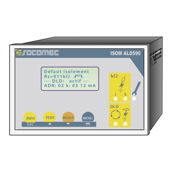
ISOM ALD590
I n s u l a t i o n F a u l t
W
R s = 0 1 1 k
. H
- - - D L D : o n - - - a u t o - -
A D R : 0 2 k : 0 3 1 2 m A
ISOM ALD590
Insulation monitoring device for IT AC and DC systems
with integrated test generator and controller for DLD46...,
DLD47... and DLD49... systems
NT 874 682 B
Advertisement
Table of Contents

Related Manuals for socomec ISOM ALD590


Summary of Contents for socomec ISOM ALD590
- Page 1 Operating manual ISOM ALD590 I n s u l a t i o n F a u l t R s = 0 1 1 k - - - D L D : o n - - - a u t o - -...
- Page 2 SOCOMEC 1 rue de Westhouse • B.P. 10 67230 Benfeld France Tél. +33 (0)3 88 57 41 41 Fax +33 (0)3 88 74 38 98 Internet : http://www.socomec.com E-Mail : scp.spc@socomec.com Right to modifications reserved...
- Page 3 Table of Contents 1. How to use this documentation effectively ......... 9 1.1 Use for the intended purpose ............9 1.2 Safety information ................9 1.3 Warranty and liability ..............10 1.4 Explanations of symbols and warnings ........10 2. Function ................... 11 2.1 General characteristics ..............
- Page 4 Table of Contents 3. Commissioning flow chart ............21 3.1 Commissioning of the ISOM function range (1) ....21 3.2 Commissioning of the insulation fault location function (DLD) (1) ................23 4. Connection ..................27 5. Operation and setting ..............31 5.1 Operating features and displays ALD590 ........
- Page 5 Table of Contents 5.5.5 Setting the real-time clock (Clock) ..........45 5.5.6 Setting the date (Date) ..............45 5.5.7 Specifying the starting time of the automatic self test (Test) ..................... 45 5.5.8 Diagram ISOM ADVANCED ............46 5.6 DLD-SETUP menu: Settings for fault location ......47 5.6.1 DLD auto / on / off / pos / 1cycle ..........
- Page 6 Table of Contents 5.9.4 Diagram COM SETUP ..............62 5.10 PASSWORD menu ................63 5.10.1 Activating and setting the password ........63 5.10.2 Diagram PASSWORT ..............63 5.11 Menu LANGUAGE ................64 5.11.1 Setting the national language ........... 64 5.11.2 Diagram Language ................ 64 5.12 Menu SERVICE ..................
- Page 7 Table of Contents 7.3.3 Characteristic curves for the insulation fault location system DLD470 ................. 86 7.4 Ordering details ................94 7.4.1 Standard version ................94 7.4.2 Protection against dust and moisture ........94 7.4.3 Measuring instruments ..............94 7.4.4 Label for modified versions ............95 NT 874 682 B...
-
Page 9: How To Use This Documentation Effectively
1.2 Safety information General safety information In addition to this operating manual, the documentation includes the supple- mentary sheet „Important safety instructions for SOCOMEC Products“. Device-specific safety information Only one insulation monitoring device may be used in each intercon- nected IT system. -
Page 10: Warranty And Liability
1.4 Explanations of symbols and warnings The following symbols are used in SOCOMEC documentation to draw atten- tion to important information and to make it easier to find certain text pas- sages. -
Page 11: General Characteristics
Memory with real-time clock to store all alarm messages with date and time stamp RS485 interface (ISOM protocol) for data exchange with other Socomec devi- ces (RS485 electrically isolated) Remote setting of certain parameters via the Internet (option; ISOM PASS IP additionally required) Option "W":... -
Page 12: Product Description
Function Test function for DLD4... systems, incl. the connected measuring current transfor. 2.4 Product description The ALD590 ISOM monitors the insulation resistance of IT systems. It is sui- table for universal use in 3(N)AC, AC/DC and DC systems. AC systems may include extensive DC supplied loads, such as converters or thyristor-control- led DC drives. - Page 13 Function associated alarm relays respond and the alarm LEDs "ALARM1/2" light up and the measuring value is indicated on the LC display (in the event of DC insulation faults, the faulty supply line is indicated). The fault indication can be stored by bridging the terminals R1/R2 (external RESET button [NC con- tact]) or by setting the fault memory to "Memory:on"...
- Page 14 Function 2.5.3 Insulation fault location Another function of the ALD590 is selective insulation fault location. If the value of the insulation resistance falls below the set response values ALARM 1 and ALARM 2, a certain test current is generated by the ALD590. The maxi- mum value of the test current is determined by the maxPuls parameter, see page 49.
- Page 15 Function monitoring will be started. Using this function, selective disconnection of an ALD590 in interconnected IT systems can be carried out via auxiliary con- tacts of the respective coupling switch. One coupling switch each in a line- type or ring-type arrangement can deactivate a subsequent ALD590. This ar- rangement guarantees that only one ISOM is active in each galvanically con- nected IT system.
- Page 16 Function 2.5.6 ISOMnet function for central control of the insulation monitoring process when several ALD590 are interconnected in IT systems. Up to 32 ISOM can communicate with each other in an ISOMnet network. The ISOMnet network can only be activated when a ISOM bus is used for interconnection.
- Page 17 Function manently carried out. Bus ISOM (A/B, RS485) Addr. 1 Addr. 2 AL590 AL590 IT-System 1 IT-System 2 IT-System 4 IT-System 3 Addr. 4 Addr. 3 AL590 AL590 This has the advantage that no auxiliary contacts of a coupling switch are required.
- Page 18 1. Press the TEST button 2. Switch the supply voltage on and off 3. Please contact Socomec If the on/off switching of the supply voltage is not possible for technical reasons, a RESET of the device can be carried out by pressing the "ESC", "RESET"...
- Page 19 Function 2.5.8 Relay K3: device fault alarm and DLD common message Relay K3 is intended to signal device and connection errors of the ISOM. In the Master mode with bus address 1, DLD alarm messages can be collectively indicated by the K3 relay as well as system fault messages. Col- lective indication of the DLD alarms by K3 can be disabled by selecting „K3 Alarm: off“...
- Page 20 Function NT 874 682 B...
Need help?
Do you have a question about the ISOM ALD590 and is the answer not in the manual?
Questions and answers