Table of Contents
Advertisement
Quick Links
v.LiNK Video-inserter
CI-RL2-MZD
Compatible with
MAZDA vehicles
with MZD Connect infotainment and 7inch monitor
Video-inserter for rear-view camera
and two additional video sources
Product features
Video-inserter for factory-infotainment systems
2 CVBS video-inputs for after-market devices (e.g. USB-player, DVB-T2 tuner)
Rear-view camera CVBS video-input
Automatic switching to rear-view camera input on engagement of the reverse gear
Video-in-motion (ONLY for connected video-sources)
Video-inputs PAL/NTSC compatible
Version 03.05.2019
HW: CAM(V31)/(V22)
CI-RL2-MTC
Advertisement
Table of Contents

Related Manuals for Car-Interface CI-RL2-MZD


Summary of Contents for Car-Interface CI-RL2-MZD
- Page 1 Video-inserter CI-RL2-MZD Compatible with MAZDA vehicles with MZD Connect infotainment and 7inch monitor Video-inserter for rear-view camera and two additional video sources Product features Video-inserter for factory-infotainment systems 2 CVBS video-inputs for after-market devices (e.g. USB-player, DVB-T2 tuner) ...
-
Page 2: Table Of Contents
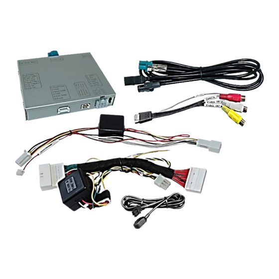
Contents 1. Prior to installation 1.1. Delivery contents 1.2. Checking the compatibility of vehicle and accessories 1.3. Boxes and connectors 1.3.1. Video-Interface 1.3.2. Dip-switch settings – interface 1.3.2.1. Enabling the interface’s video inputs (dip 2-3) 1.3.2.2. Rear-view camera setting (dip 5) 2. -
Page 3: Prior To Installation
Legal Information By law, watching moving pictures while driving is prohibited, the driver must not be distracted. We do not accept any liability for material damage or personal injury resulting, directly or indirectly, from installation or operation of this product. Apart from using this product in an unmoved vehicle, it should only be used to display fixed menus or rear-view- camera video when the vehicle is moving (for example the MP3 menu for DVD upgrades). -
Page 4: Checking The Compatibility Of Vehicle And Accessories
1.2. Checking the compatibility of vehicle and accessories Requirements Brand Compatible vehicles Compatible systems 2,3,5,6,8 Biante MZD Connect infotainment CX-5 Mazda with 7inch monitor CX-9 MX-5 Limitations: Video only The interface inserts ONLY video signals into the infotainment. For inserting Audio signals either the possibly existing factory audio-AUX-input or a FM- modulator can be used. -
Page 5: Dip-Switch Settings - Interface
1.3.2. Dip-switch settings – interface Some settings have to be selected by the dip-switches on the video interface. Dip position down is ON and position up is OFF. Function ON (down) OFF (up) No function set to OFF CVBS AV1-input enabled disabled CVBS AV2-input... -
Page 6: Installation
2. Installation To install the interface, first switch off the ignition and disconnect the vehicle’s battery. Please read the owner`s manual of the car, regarding the battery`s disconnection! If required, enable the car`s Sleep-mode (hibernation mode) In case the sleep-mode does not succeed, the disconnection of the battery can be done with a resistor lead. -
Page 7: Connection Schema
2.2. Connection schema Version 03.05.2019 HW: CAM(V31)/(V22) CI-RL2-MTC... -
Page 8: Connection - Video-Interface And Power/Can
2.3. Connection - video-interface and Power / CAN Connect the 6pin cable’s white female 6pin pin connector to the male 6pin connector of the video interface. Connect the 6pin cable’s yellow coloured wire “TO ACC” to ACC terminal15 or S-contact terminal 86s. Disconnect the female 28pin connector of the factory harness at the rear-side of the head unit and connect it to the 28pin PNP cable’s male 28pin connector. -
Page 9: Connection - Picture Signal Cable
2.4. Connection - picture signal cable Connect the enclosed picture signal cable’s female waterblue coloured HSD+2 connector to the male waterblue coloured HSD+2 connector of the video interface. Disconnect the factory picture signal cable’s female 4pin connector at the rear side of the factory monitor and connect it to the black male 4pin connector of the enclosed picture signal cable. -
Page 10: Connection - Filter And Fuse Box
2.5. Connection – Filter and fuse box Connect the filter and fuse box cable’s small female 8pin connector to the male 8pin connector of the video interface. Disconnect the factory cable’s female 8pin connector at the rear-side of the factory monitor and connect it to the filter and fuse box cable’s male 8pin connector. -
Page 11: Connection - Video Sources
2.6. Connection - Video-sources It is possible to connect two after-market video sources and one after-market rear-view camera to the video-interface. Before final installation of the peripheral devices, we recommend a test-run to detect a incompatibility of vehicle and interface. Due to changes in the production of the vehicle manufacturer there’s always a possibility of incompatibility. -
Page 12: After-Market Rear-View Camera
2.7. After-market rear-view camera For the function of the rear-view camera, an external switching signal from the reverse gear light is required. As the reverse gear light signal contains electronic interference, use a traditional open relay (e.g AC-RW-1230 with wiring AC-RS5) or filter (e.g. AC-PNF-RVC). The schema below shows the use of a relay (normally open). -
Page 13: Connection - Video Interface And External Keypad
2.8. Connection - video-interface and external keypad Connect the keypad’s female 4pin connector to the video-interface’s male 4pin connector. Note: Even if the switching through several video sources by the keypad mightn’t be required, the invisible connection and availability is strongly recommended. Version 03.05.2019 HW: CAM(V31)/(V22) CI-RL2-MTC... -
Page 14: Picture Settings
2.9. Picture settings and guide lines The picture settings are adjustable by the 3 push-buttons on the video-interface. Press the MENU button to open the OSD settings menu or to switch to the next menu item. Press UP and DOWN to change the selected value. The buttons are placed inside in the housing to avoid accidental changes during or after the installation. -
Page 15: Video Interface Operation
3. Video interface operation 3.1. By infotainment buttons To switch the video sources the vehicle’s infotainment button at the steering wheel can be used. A press of the steering wheel’s “Call Off” key switches to the next activated video input. If all inputs are enabled the order is: ... -
Page 16: By External Keypad
3.2. By external keypad Alternatively or additionally to the factory infotainment buttons, the interface’s external keypad can be used to switch the enabled inputs. 3.3. By white wire of the 6pin cable Alternatively or additionally to the factory infotainment button, the white wire of the 6pin cable can be used to switch the enabled inputs. -
Page 17: Faq - Trouble Shooting-Interface Functions
FAQ – Trouble shooting Interface functions For any troubles which may occur, check the following table for a solution before requesting support from your vendor. Symptom Reason Possible solution Not all connectors have been reconnected to factory head- Connect missing connectors. unit or monitor after installation. - Page 18 Symptom Reason Possible solution Camera input picture Use relay or electronics to "clean" reverse gear lamp black. Camera power taken directly power. Alternatively, if CAN-bus box is compatible Camera input picture from reverse gear lamp. with the vehicle, camera power can be taken from green wire of 6pin to 8pin cable.
Need help?
Do you have a question about the CI-RL2-MZD and is the answer not in the manual?
Questions and answers