Table of Contents
Advertisement
Quick Links
Compatible with Opel vehicles with
Navi 900 intelliLink navigation systems
Video-inserter with front + rear-view camera + one more video input and CAN
Product features
Video-inserter for factory-navigation monitors
Back- und front Kamera CVBS Input
CVBS Video-Input for after-market Video sources (e.g. DVD-Player, DVB-T Tuner, ...)
Automatic switching to rear-view camera input on engagement of the reverse gear
Switching to Front camera by keypad
Activatable parking guide lines for rear-view camera (vehicle specific restrictions
possible)
Video-in-motion (ONLY for connected video-sources)
Compatible with factory rear-view camera
Version 16.02.2017
r.LiNK Video-inserter
CI-RL2-N900
with 8" Touch-Monitor
control
Advertisement
Table of Contents

Related Manuals for Car-Interface r.LiNK CI-RL2-N900


Summary of Contents for Car-Interface r.LiNK CI-RL2-N900
- Page 1 r.LiNK Video-inserter CI-RL2-N900 Compatible with Opel vehicles with Navi 900 intelliLink navigation systems with 8” Touch-Monitor Video-inserter with front + rear-view camera + one more video input and CAN control Product features Video-inserter for factory-navigation monitors Back- und front Kamera CVBS Input ...
-
Page 2: Table Of Contents
Contents 1. Prior to installation 1.1. Delivery contents 1.2. Checking the compatibility of vehicle and accessories 1.3. Boxes and connectors 1.3.1. Video-Interface 1.3.2. CAN-bus box 1.3.2.1. Dip-switch settings 1.3.2.2. Enabling the interface’s video inputs (dip 2-3) 1.3.2.3. Rear-view camera setting (dip 5) 1.3.2.4. -
Page 3: Prior To Installation
Legal Information By law, watching moving pictures while driving is prohibited because the driver must not be distracted. We do not accept any liability for material damage or personal injury resulting, directly or indirectly, from installation or operation of this product. Apart from using this product in an unmoved vehicle, it should only be used to display fixed menus or rear-view- camera video when the vehicle is moving (for example the MP3 menu for DVD upgrades). -
Page 4: Checking The Compatibility Of Vehicle And Accessories
1.2. Checking the compatibility of vehicle and accessories Requirements Vehicle Opel Astra K since Model year 2016, Insignia A since Model year 2014, Mokka X since Model year 2016 Head-unit/monitor Navi-900 intelliLink with 8” Monitor (Gen. 1 and 2) Limitations Video only The interface inserts ONLY video signals into the infotainment. -
Page 5: Can-Bus Box
1.3.2. CAN-bus box The CAN box reads the vehicle’s digital signals out of the vehicle’s CAN-bus and converts them for the video interface. 1.3.2.1. Dip-switch settings Some settings must be selected by the dip-switches on the video interface. Dip position down is ON and position up is OFF. Function ON (down) OFF (up) -
Page 6: Monitor Selection (Dip 7-8)
1.3.2.4. Monitor selection (dip 7-8) Dip 7 and 8 customize the monitor-specific video settings which sometimes even vary within head units of the same version, caused by different monitor specifications. It is necessary to try all possible combinations (both OFF, both ON, 7 OFF and 8 ON, 7 ON and 8 OFF) while a working video source is connected to the chosen input of the interface. -
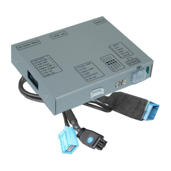
Page 7: Connection Schema
2.2. Connection schema Version 16.02.2017 CI-RL2-N900... -
Page 8: Connecting Video-Interface And Can-Box
2.3. Connecting video-interface and CAN-box Connect the black female 6pin Micro-Fit connector of the PNP Power/CAN harness to the male 6pin Micro-Fit connector of the CAN-box. Note: Check the LEDs on the CAN-box after reconnecting the battery-two must be on. Connect the white female 6pin Molex connector of the 6pin to 12pin cable to the male 6pin Molex connector of the video-interface. - Page 9 2.4. Connections to the monitor Remove factory monitor. Connect the female 8pin Micro-Fit connector of the Mini USB Video cable to male 8-pin Micro-Fit connector of the video-interface. Disconnect the male Mini USB connector of the Mini USB vehicle harness from the monitor’s Rear side and connect it to the female Mini USB connector of the Mini USB Video Cable Connect the male Mini USB connector of the Mini USB Video cable with the female...
-
Page 10: Connecting Of Peripheral Devices
2.5. Connecting peripheral devices It is possible to connect one after-market rear-view camera, one after-market Front camera and one after-market Video source to the video-interface. Before final installation of the peripheral devices, we recommend a test-run to detect a incompatibility of vehicle and interface. Due to changes in the production of the vehicle manufacturer there’s always a possibility of incompatibility. -
Page 11: Case 2: Can-Box Does Not Receive The Reverse Gear Signal
2.5.1.2. Case 2: CAN-box does not receive the reverse gear signal If the CAN-bus interface does not deliver +12V on the green wire of the 6pin to 12pin cable when reverse gear is engaged (not all vehicles are compatible) an external switching signal from the reverse gear light is required. -
Page 12: Connection To The Rear View Camera's Video Signal
2.5.1.3. Connecting the rear-view camera’s Video signal Connect the female 6-pin connector of the Video cable to the male 6-pin connector of the interface Connect the male RCA connector of the Rear-view camera to the white female RCA “CAMERA IN” of the Video cable 2.5.2. -
Page 13: After-Market Video Source
2.5.3. After-market Video source Connect the female 6pin connector of the video cable to male 6pin connector of the video-interface. Connect the male video-RCA connector of the Video source to the yellow female RCA port of the video-interface which is labelled as “Video IN2”. 2.5.4. -
Page 14: Picture Settings And Guide Lines
2.7. Picture settings and guide lines The picture settings are adjustable by the 3 push-buttons on the video-interface. Press the MENU button to open the OSD settings menu or to switch to the next menu item. Press UP and DOWN to change the selected value. The buttons are placed inside in the housing to avoid accidental changes during or after the installation. -
Page 15: Interface Operation
3. Interface operation To operate the interface functions, the external keypad can be used. Each press will switch to the next enabled input. Disabled inputs will be skipped. 4. Specifications BATT/ACC range 7V - 25V Stand-by power drain <10mA Power 0.7A @12V Video input 0.7V - 1V... -
Page 16: Faq - Trouble Shooting-Interface Functions
FAQ – Trouble shooting Interface functions For any troubles which may occur, check the following table for a solution before requesting support from your vendor. Symptom Reason Possible solution Not all connectors have been reconnected to factory head- Connect missing connectors. unit or monitor after installation. - Page 17 Symptom Reason Possible solution Camera input picture Use relay or electronics to "clean" reverse gear lamp black. Camera power taken directly power. Alternatively, if CAN-bus box is compatible Camera input picture from reverse gear lamp. with the vehicle, camera power can be taken from green wire of 6pin to 8pin cable.
Need help?
Do you have a question about the r.LiNK CI-RL2-N900 and is the answer not in the manual?
Questions and answers