Table of Contents
Advertisement
Quick Links
Video-inserter for front- and rear-view camera
Product features
Video-inserter for factory-infotainment systems
1 CVBS Input for rear-view camera
1 CVBS Input for front camera
2 CVBS video-inputs for after-market devices (e.g. 2 mirror cameras, USB-Player,
DVB-T2 tuner)
Automatic switching to rear-view camera input on engagement of the reverse gear
Automatic front camera switching after reverse gear for 10, 15 or 20 seconds
(adjustable)
Activatable parking guide lines for rear-view camera in combination with PDC
display (not available for all vehicles)
Video-in-motion (ONLY for connected video-sources)
Video-inputs NTSC compatible
Version 03.05.2021
r.LiNK Video-inserter
CI-RL4-NAC12
Compatible with
Opel and Peugeot vehicles
with NAC infotainment
and two additional video inputs
HW: BOT(V40)(V54)
CI-RL4-NAC12
Advertisement
Table of Contents

Related Manuals for Car-Interface CI-RL4-NAC12


Summary of Contents for Car-Interface CI-RL4-NAC12
- Page 1 Video-inserter CI-RL4-NAC12 Compatible with Opel and Peugeot vehicles with NAC infotainment Video-inserter for front- and rear-view camera and two additional video inputs Product features Video-inserter for factory-infotainment systems 1 CVBS Input for rear-view camera 1 CVBS Input for front camera ...
-
Page 2: Table Of Contents
Case 2: Video interface does not receive the reverse gear signal 2.5.3. After-market front camera 2.5.4. After-market mirror cameras 2.6. Connection - external keypad 2.7. Picture settings 3. Interface operation 4. Specifications 5. FAQ – Trouble shooting Version 03.05.2021 HW: BOT(V40)(V54) CI-RL4-NAC12... -
Page 3: Prior To Installation
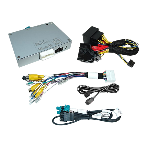
Read the manual prior to installation. Technical knowledge is necessary for installation. The place of installation must be free of moisture and away from heat sources. 1.1. Delivery contents Take down the serial number of the interface and store this manual for support purposes: ____________________ Version 03.05.2021 HW: BOT(V40)(V54) CI-RL4-NAC12... -
Page 4: Checking The Compatibility Of Vehicle And Accessories
If mirror cameras are connected, use only cameras which are resistant to continuous current. Guidelines and PDC Displayed guidelines and PDC are not available in all vehicles. Guidelines can only be displayed together with PDC. Version 03.05.2021 HW: BOT(V40)(V54) CI-RL4-NAC12... -
Page 5: Warning Notes
(single black male 4pin HSD on backside) high version head-unit (double black male 4pin HSD on the backside) Please, carefully follow the manual for high or low version connection of the head unit! Version 03.05.2021 HW: BOT(V40)(V54) CI-RL4-NAC12... -
Page 6: Connection Video-Interface
Further it reads the vehicle’s digital signals out of the vehicle’s CAN-bus and converts them for the video interface. Version 03.05.2021 HW: BOT(V40)(V54) CI-RL4-NAC12... -
Page 7: Settings Of The 8 Dip Switches
+12V when the front camera is manually selected by external keypad (see chapter "Power Supply Output"). **The display of the guidelines only works with simultaneous PDC display (Dip8 = ON). After each Dip-switch-change a power-reset of the Can-box has to be performed! Version 03.05.2021 HW: BOT(V40)(V54) CI-RL4-NAC12... -
Page 8: Enabling The Interface's Video Inputs Av1-R And Av2-L (Dip 1-2)
If there is no communication between interface and the vehicle`s CAN-bus (several vehicles aren’t compatible), the reverse gear guide-lines can`t be shown during the vehicle’s operation, even if they once appear after having switched the system to powerless! Version 03.05.2021 HW: BOT(V40)(V54) CI-RL4-NAC12... -
Page 9: Activating The Factory Pdc Display (Dip-8)
Before the final installation, we recommend a test-run of the interface. Due to changes in the production of the vehicle manufacturer, there’s always the possibility of incompatibility. 2.1. Place of installation – video-interface The video-interface is performed to be installed at the head unit’s rear side. Version 03.05.2021 HW: BOT(V40)(V54) CI-RL4-NAC12... -
Page 10: Connection Schema
2.2. Connection schema Version 03.05.2021 HW: BOT(V40)(V54) CI-RL4-NAC12... -
Page 11: Connection - Head-Unit
Connector of the 4pin HSD harness to the previously become free double 4pin HSD connector of the head unit. Connect the single waterblue colored 4pin HSD connector of that harness to the waterblue colored 4pin HSD connector of the video interface. Version 03.05.2021 HW: BOT(V40)(V54) CI-RL4-NAC12... -
Page 12: Low Version Head Unit (1 X 4Pin Hsd)
4pin HSD connector at the rearside of the head unit. Connect the waterblue colored female 4pin HSD connector „to interface“ to the waterblue colored 4pin HSD connector of the video interface. Version 03.05.2021 HW: BOT(V40)(V54) CI-RL4-NAC12... -
Page 13: Connection- Power / Can
Connect the opposite female quadlock connectorof the enclosed10pin power/CAN cable to the previously released quadlock connector of the Head Unit. Connect the power / CAN cable’s female 10pin connector to the 10pin connector of the video interface. Version 03.05.2021 HW: BOT(V40)(V54) CI-RL4-NAC12... -
Page 14: Analog Power Supply For The Video Interface
Note: In case the analogue connection has to be made (because some vehicles are not compatible), the input signal for each connected video source must also be manually triggered via the corresponding 4 trigger lines Trig-REAR/Trig-FRONT/Trig-RIGHT/Trig-LEFT For analogue connection, dont forget to set dip4 to OFF! Version 03.05.2021 HW: BOT(V40)(V54) CI-RL4-NAC12... -
Page 15: Power Supply Output
Attention: If mirror cameras shell be energized, only continuous current-resistant cameras are allowed to be connected to the red wire „ACC-out” as ,otherwise, non-resistent cameras would be damaged. Continuous current-resistance is supported by our following cameras: CAM-E-B168 CAM-E-B180 CAM-E-B113 Version 03.05.2021 HW: BOT(V40)(V54) CI-RL4-NAC12... -
Page 16: Connection - Video Sources
Connect the front camera’s video RCA connector to the 12pin interface cable’s female RCA connector „V3 Front“. Connect the video RCAs of the AV source 1 and 2 or alternatively of two mirror cameras to the 12pin interface cable’s female RCA connector “AV1 Left” ”AV2 Right”. Version 03.05.2021 HW: BOT(V40)(V54) CI-RL4-NAC12... -
Page 17: Audio Insertion
Reverse“while reverse gear is engaged. The 12 V power supply for the rear-view camera (max 3A) has to be taken from the green wire “Reverse-OUT”of the 20pin cable to avoid an unnecessary, permanent power supply to the camera electronic. Version 03.05.2021 HW: BOT(V40)(V54) CI-RL4-NAC12... -
Page 18: Case 2: Video Interface Does Not Receive The Reverse Gear Signal
Note: If, due to a missing CAN communication, interface has been connected the analogue way, the green wire’s connection has also to be done as shown in the picture above. For analogue connection, dont forget to set dip4 to OFF! Version 03.05.2021 HW: BOT(V40)(V54) CI-RL4-NAC12... -
Page 19: After-Market Front Camera
Note: In addition, a manual switch-over to the front camera input is possible via keypad (short press) from any image mode. The power supply output supplies +12V then, too (if Dip 3 is set to ON and the front camera input is selected). Version 03.05.2021 HW: BOT(V40)(V54) CI-RL4-NAC12... -
Page 20: After-Market Mirror Cameras
Attention: To energize the mirror camaras, only continuous current-resistant cameras may be connected to the red line „ACC-out“, as they would otherwise be damaged. Our following cameras are among others resistant to continuous current: CAM-E-B168 CAM-E-B180 CAM-E-b113 Version 03.05.2021 HW: BOT(V40)(V54) CI-RL4-NAC12... -
Page 21: Connection - External Keypad
Connect the keypad’s female 4pin connector to the 20pin interface cable’s male 4pin connector. Note: Even if the switching through several video sources by the keypad mightn’t be required, the invisible connection and availability is strongly recommended. Version 03.05.2021 HW: BOT(V40)(V54) CI-RL4-NAC12... -
Page 22: Picture Settings
The following settings are available: Contrast Brightness Saturation Pos H (horizontal) Pos V (vertical) Front Front camera switch back Duration adjustable for 10, 15 or 20 seconds (10 seconds is preset) Version 03.05.2021 HW: BOT(V40)(V54) CI-RL4-NAC12... -
Page 23: Interface Operation
7V - 25V Stand-by power drain Power 280mA @12V Video input 0.7V – 1V Video input formats NTSC Temperature range -40°C to +85°C Dimensions Video-Box 117 x 25 x 108 mm (W x H x D) Version 03.05.2021 HW: BOT(V40)(V54) CI-RL4-NAC12... -
Page 24: Faq - Trouble Shooting
Camera input picture fluorescent light which shines Test camera under natural light outside the garage. flickers. directly into the camera. Camera input picture is Protection sticker not Remove protection sticker from lens. bluish. removed from camera lens. Version 03.05.2021 HW: BOT(V40)(V54) CI-RL4-NAC12... - Page 25 Cut the grey wire of 6pin to 8pin and isolate both Interface switches compatibility to vehicle is ends. If problem still occurs, additionally cut the white video-sources by itself. limited. wire of 6pin to 8pin cable and isolate both ends. 10R-05 0068 Made in China Version 03.05.2021 HW: BOT(V40)(V54) CI-RL4-NAC12...
Need help?
Do you have a question about the CI-RL4-NAC12 and is the answer not in the manual?
Questions and answers