Table of Contents
Advertisement
Quick Links
Dacia, Fiat, Smart and Renault vehicles
with RLink or MediaNav system
and Opel vehicles with Navi 50 or Navi 80
Video-inserter with 2 video inputs and rear-view camera input
Product features
Video-inserter for factory-infotainment systems
2 video-inputs for after-market devices (e.g. DVD-Player, DVB-T tuner)
Rear-view camera video-input
Automatic switching to rear-view camera input on engagement of the reverse gear
Activatable parking guide lines for rear-view camera (not for all vehicles available)
Video-in-motion (ONLY for connected video-sources)
Video-inputs PAL / NTSC compatible
Version 08.04.2021
r.LiNK Video-inserter
CI-RL2-RLINK
Compatible with
HW CAM(V31)/(V22)
CI-RL2-RLINK
Advertisement
Table of Contents

Related Manuals for Car-Interface r.LiNK CI-RL2-RLINK


Summary of Contents for Car-Interface r.LiNK CI-RL2-RLINK
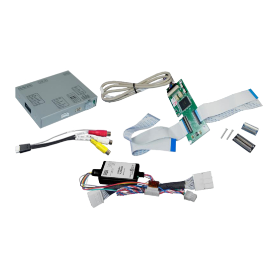
- Page 1 r.LiNK Video-inserter CI-RL2-RLINK Compatible with Dacia, Fiat, Smart and Renault vehicles with RLink or MediaNav system and Opel vehicles with Navi 50 or Navi 80 Video-inserter with 2 video inputs and rear-view camera input Product features Video-inserter for factory-infotainment systems ...
-
Page 2: Table Of Contents
Contents 1. Prior to installation 1.1. Delivery contents 1.2. Checking the Interface compatibility of vehicle and accessories 1.3. Boxes and connectors 1.3.1. Video-interface 1.3.1.1. Dip-switch settings 1.3.1.2. Enabling the interface’s video inputs (dip 2-3) 1.3.1.3. Rear-view camera setting (dip 5) 1.3.1.4. -
Page 3: Prior To Installation
Legal Information By law, watching moving pictures while driving is prohibited, the driver must not be distracted. We do not accept any liability for material damage or personal injury resulting, directly or indirectly, from installation or operation of this product. This product should only be used while standing or to display fixed menus or rear-view-camera video when the vehicle is moving, for example the MP3 menu for DVD upgrades. -
Page 4: Checking The Interface Compatibility Of Vehicle And Accessories
1.2. Checking the compatibility of vehicle and accessories Requirements Brand Compatible vehicles Compatible systems Dokker since 2013-, Duster since 2014, Lodgy since Dacia MediaNav 2012, Logan since 2013, Sandero since 2012 Fiat Talento model year since 2016 MediaNav Navi 50 (MediaNav), Opel Movano since about 2016, Vivaro since about 2016 Navi 80 IntelliLink (Rlink) -
Page 5: Dip-Switch Settings
1.3.1.1. Dip-switch settings Some settings must be selected by the dip-switches on the video-interface. Dip position down is ON and position up is OFF. Function ON (down) OFF (up) No function set to OFF CVBS AV1-input enabled disabled CVBS AV2-input enabled disabled No function... -
Page 6: Can-Box
1.3.2. CAN-box The CAN-box reads digital signals from the CAN-bus and converts them for the video- interface. 2. Installation Switch off ignition and disconnect the vehicle’s battery! The interface needs a permanent 12V source. If according to factory rules disconnecting the battery is to be avoided, it is usually sufficient to put the vehicle to “Sleep-Mode”. -
Page 7: Connection Scheme
2.2. Connection Scheme Version 08.04.2021 HW CAM(V31)/(V22) CI-RL2-RLINK... -
Page 8: Connecting Video-Interface And Can-Box
2.3. Connecting video-interface and CAN-Box The CAN-box reads digital signals from the CAN-bus and converts them for the video- interface. ACC +12V max. 0.5A (red of 6pin) and reverse gear +12V max. 0.5A constant signal (green of 6pin). Video-source switching (white of 6pin) as +12V impulse. The grey wire stays unconnected. - Page 9 2.4. Installation of the Ribbon cables into the Monitor panel Remove the factory monitor and open it`s housing. The external daughter PCB is built to be installed into the optical lead between the monitor panel and mainboard of the vehicles monitor.
-
Page 10: Warning Notes, Concerning The Installation Of Ribbon Cables
2.4.1. Media Nav with 50pin Ribbon cable Disconnect the optical leads housed between the monitor`s mainboard and the monitor- panel. Connect the daughter PCB’s ribbon cable CAR-IN to the ribbon cable base of the monitor`s mainboard. For this procedure you may either use the original ribbon cable or the ribbon cable of the daughter PCB. - Page 11 2.4.2. R-Link with 60pin Flex cable Remove the Ribbon cable between the monitor’s monitor panel and the monitor PCB. Connect the daughter PCB’s ribbon cable CAR-IN to the ribbon cable base of the main PCB. For this procedure you may either use the original ribbon cable or the ribbon cable of daughter PCB.
-
Page 12: Rlink With 60Pin Ribbon Cable
2.5. Connection to the head unit- Power and CAN Depending on the system (MediNav or RLink) there`re to different Power-and Can connections required. For the MediaNav installation the enclosed PNP harness is not usable 2.5.1. MediaNav with 50pin Ribbon cable Remove the vehicle`s monitor. -
Page 13: Connection Of Video Sources
2.6. Connecting video sources It is possible to connect two after-market video sources and one after-market rear-view camera to the video-interface. Before final installation of the peripheral devices, we recommend a test-run to detect a incompatibility of vehicle and interface. Due to changes in the production of the vehicle manufacturer there’s always a possibility of incompatibility. -
Page 14: Audio-Insertion
2.6.1. Audio-insertion This interface is only able to insert video signals into the factory infotainment. If an AV- source is connected, the audio insertion has to be done by the factory audio AUX input or an FM-modulator. The inserted video-signal can be activated simultaneously to each audio- mode of the factory infotainment. - Page 15 2.6.2.2. Case 2: CAN-box does not receive the reverse gear signal If the CAN-bus interface does not receive +12V on the green wire of the 6pin to 8pin cable when reverse gear is engaged (not all vehicles are compatible) an external switching signal from the reverse gear light is required.
-
Page 16: Connecting Video-Interface And Keypad
2.7. Connecting video-interface and keypad Connect the keypad’s female 4pin connector to the male 4pin connector of the video- interface. Note: Even if the switching through several video sources by the keypad mightn’t be required, the keypad’s invisible connection and availability is strongly recommended. Version 08.04.2021 HW CAM(V31)/(V22) CI-RL2-RLINK... -
Page 17: Picture Settings And Parking Guide Lines
2.8. Picture settings and Guide Lines The picture settings are adjusted by the 3 buttons on the video-interface. Press the MENU button to open the OSD settings menu or to switch to the next menu item. Press UP and DOWN change the selected value. The buttons are embedded in the housing to avoid accidental changes during or after installation. -
Page 18: Interface Operation
3. Interface operation 3.1. By VOL- button Press VOL- on steering-wheel 2x quickly to switch the video source. Each repetition will switch to the next enabled input. If all inputs are enabled the order is: Factory video video IN1 video IN2 factory video... - Page 19 FAQ – Trouble shooting Interface functions For any troubles which may occur, check the following table for a solution before requesting support from your vendor. Symptom Reason Possible solution Not all connectors have been reconnected to factory head- Connect missing connectors. unit or monitor after installation.
- Page 20 Symptom Reason Possible solution Camera input picture Use relay or electronics to "clean" reverse gear lamp black. Camera power taken directly power. Alternatively, if CAN-bus box is compatible Camera input picture from reverse gear lamp. with the vehicle, camera power can be taken from green wire of 6pin to 8pin cable.
Need help?
Do you have a question about the r.LiNK CI-RL2-RLINK and is the answer not in the manual?
Questions and answers