Table of Contents
Advertisement
Quick Links
v.LiNK Video-inserter
CI-RL2-MTC
Compatible with
MASERATI vehicles
with Maserati Touch Control (MTC) infotainment
Video-inserter with 2 video inputs, rear-view camera input
and CAN-bus communikation
Product features
Video-inserter for factory-infotainment systems
2 CVBS video-inputs for after-market devices (e.g. USB-player, DVB-T2 tuner)
Rear-view camera CVBS video-input
Automatic switching to rear-view camera input on engagement of the reverse gear
Video-in-motion (ONLY for connected video-sources)
Video-inputs NTSC and PAL compatible
Version 24.09.2020
HW: CAM(V31)/(V22)
CI-RL2-MTC
Advertisement
Table of Contents

Related Manuals for Car-Interface CI-RL2-MTC


Summary of Contents for Car-Interface CI-RL2-MTC
- Page 1 Video-inserter CI-RL2-MTC Compatible with MASERATI vehicles with Maserati Touch Control (MTC) infotainment Video-inserter with 2 video inputs, rear-view camera input and CAN-bus communikation Product features Video-inserter for factory-infotainment systems 2 CVBS video-inputs for after-market devices (e.g. USB-player, DVB-T2 tuner) ...
-
Page 2: Table Of Contents
Connection – video interface and external keypad 2.9. Picture settings 3. Video interface operation 3.1. By infotainment button 3.2. By external keypad 3.3. By white wire of the 6pin to 8pin cable 4. Specifications 5. FAQ – Trouble Shooting-Interface functions Version 24.09.2020 HW: CAM(V31)/(V22) CI-RL2-MTC... -
Page 3: Prior To Installation
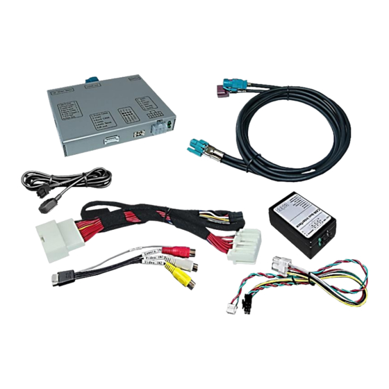
Read the manual prior to installation. Technical knowledge is necessary for installation. The place of installation must be free of moisture and away from heat sources. 1.1. Delivery contents Take down the serial number of the interface and store this manual for support purposes: ____________________ Version 24.09.2020 HW: CAM(V31)/(V22) CI-RL2-MTC... -
Page 4: Checking The Compatibility Of Vehicle And Accessories
Factory rear-view camera Automatically switching-back from inserted video to factory rear-view camera is only possible while the reverse gear is engaged. To delay the switch-back an additional electronic part is required. Version 24.09.2020 HW: CAM(V31)/(V22) CI-RL2-MTC... -
Page 5: Boxes And Connectors
Further it reads the vehicle’s digital signals out of the vehicle’s CAN-bus and converts them for the video interface. 1.3.2. CAN-bus box The CAN box reads the vehicle’s digital signals out of the vehicle’s CAN-bus and converts them for the video interface. Version 24.09.2020 HW: CAM(V31)/(V22) CI-RL2-MTC... -
Page 6: Dip-Switch Settings - Interface
Dip switch setting ON will support the 4.3inch monitor. Dip switch setting OFF will support the 8.4inch monitor. Note: Dip 1, 4, 6 and 7 are out of function and have to be set to OFF. Version 24.09.2020 HW: CAM(V31)/(V22) CI-RL2-MTC... -
Page 7: Installation
2.1.1. Place of installation – video interface and CAN-bus box The interface box and the CAN-bus box are prepared to be connected behind the vehicle`s monitor and head-unit. Both parts have to be removed for the installation Version 24.09.2020 HW: CAM(V31)/(V22) CI-RL2-MTC... -
Page 8: Connection Schema
2.2. Connection schema Version 24.09.2020 HW: CAM(V31)/(V22) CI-RL2-MTC... -
Page 9: Connection - Video-Interface And Power/Can
22pin PNP cable’s male 22pin connector. Connect the 22pin PNP cable’s opposite female 22pin connector to the previously become free male 22pin connector at the rear-side of the head unit. Version 24.09.2020 HW: CAM(V31)/(V22) CI-RL2-MTC... -
Page 10: Analogue Connection - Video-Interface
Note: The connection of the green wire (Reverse signal) will be described in chapter “After- market rear-view camera”. The white wire, can be used to switch the enabled video sources , same as the keypad (see chapter “video interface-operation”). The grey wire stays unconnected. Version 24.09.2020 HW: CAM(V31)/(V22) CI-RL2-MTC... -
Page 11: Connection - Picture Signal Cable
Attention: The factory picture signal cable has to be kept connected to the head unit during the installation prozess! Connect the picture signal cable’s waterblue coloured female 4pin HSD connector to the previously become free white coloured male 4pin HSD connector at the rear side of the factory monitor. Version 24.09.2020 HW: CAM(V31)/(V22) CI-RL2-MTC... -
Page 12: Connection - Video Sources
Connect the RCA of the video source 1 and video source 2 to the video cable’s female „Video IN1“ and „Video IN2“. Connect the rear-view camera’s RCA to the video cable’s female RCA „Camera IN“. Version 24.09.2020 HW: CAM(V31)/(V22) CI-RL2-MTC... -
Page 13: After-Market Rear-View Camera
„CAMERA IN“ while the reverse gear is engaged. Additionally, the +12V (max. 500mA) power supply for the rear-view camera can be taken from the green wire of the 6pin to 8pin cable. Version 24.09.2020 HW: CAM(V31)/(V22) CI-RL2-MTC... -
Page 14: Case 2: Can-Box Does Not Receive The Reverse Gear Signal
Note: If, due to a missing CAN communication, the 6pin to 8pin cable has been connected the analogue way instead of the Can box, the green wire’s connection has also to be done as shown in the picture above. Version 24.09.2020 HW: CAM(V31)/(V22) CI-RL2-MTC... -
Page 15: Connection - Video Interface And External Keypad
Connect the keypad’s female 4pin connector to the video-interface’s male 4pin connector. Note: Even if the switching through several video sources by the keypad mightn’t be required, the invisible connection and availability is strongly recommended. Version 24.09.2020 HW: CAM(V31)/(V22) CI-RL2-MTC... -
Page 16: Picture Settings
Note: The OSD menu is only shown when a working video source is connected to the selected video-input of the interface. The following settings are available: Contrast Brightness Saturation Position H (horizontal) Position V (vertical) IR-AV1/2 (no function) Guide L/R 8no function) UI-CNTRL (no function) Size H/V (picture size horizontal/vertical) Version 24.09.2020 HW: CAM(V31)/(V22) CI-RL2-MTC... -
Page 17: Video Interface Operation
Disabled inputs will be skipped. Switchover by vehicle buttons isn’t possible in all vehicles. In some vehicles the external keypad or the white wire of the 6pin to 8pin cable has to be used (see following chapter). Version 24.09.2020 HW: CAM(V31)/(V22) CI-RL2-MTC... -
Page 18: By External Keypad
0.7V with 75 Ohm impedance Temperature range -40°C to +85°C Dimensions video-box 112 x 23 x 111 mm (W x H x D) Dimensions CAN-box 72 x 23 x 44 mm (W x H x D) Version 24.09.2020 HW: CAM(V31)/(V22) CI-RL2-MTC... -
Page 19: Faq - Trouble Shooting-Interface Functions
Camera input picture fluorescent light which shines Test camera under natural light outside the garage. flickers. directly into the camera. Camera input picture is Protection sticker not Remove protection sticker from lens. bluish. removed from camera lens. Version 24.09.2020 HW: CAM(V31)/(V22) CI-RL2-MTC... - Page 20 Cut the grey wire of 6pin to 8pin and isolate both Interface switches compatibility to vehicle is ends. If problem still occurs, additionally cut the white video-sources by itself. limited. wire of 6pin to 8pin cable and isolate both ends. 10R-03 5384 Made in China Version 24.09.2020 HW: CAM(V31)/(V22) CI-RL2-MTC...
Need help?
Do you have a question about the CI-RL2-MTC and is the answer not in the manual?
Questions and answers